A medium and high temperature solar heat collector optical efficiency test device

A solar collector tube, optical efficiency technology, applied in solar thermal devices, solar collectors, solar thermal energy and other directions, can solve the optical efficiency error of the solar selective absorption coating, the influence of the heat loss of the solar collector tube, and the temperature measurement accuracy. Accuracy and other issues, to achieve the effects of controllable medium flow, controllable irradiation power, and accurate temperature measurement

Active Publication Date: 2015-11-04
HIMIN SOLAR
View PDF4 Cites 0 Cited by
  • Summary
  • Abstract
  • Description
  • Claims
  • Application Information

AI Technical Summary

Problems solved by technology

One is limited by the weather, because this method is to test the medium and high temperature solar heat collector tubes in a natural environment. Many natural factors (such as clouds, fog, rain) affect the fluctuation of solar irradiance. In the measurement of solar irradiance and There is a large error in the calculation process; in addition, the size of the wind speed will affect the heat loss of the medium and high temperature solar collector tube, which will bring a large error to the test of the optical efficiency of the solar selective absorption coating
Second, the temperature measurement accuracy is inaccurate, because the temperature measurement method of this method is to measure the temperature of the outer surface of the metal inner tube of the medium and high temperature solar collector tube, rather than the temperature of the medium, which eventually leads to large errors in the test results

Method used


Image

  • A medium and high temperature solar heat collector optical efficiency test device

Examples


Embodiment Construction

[0037] In order to further explain the technical means and effects of the present invention to achieve the intended purpose of the invention, the specific implementation of a medium-high temperature solar collector tube optical efficiency test device proposed according to the present invention will be described below in conjunction with the accompanying drawings and preferred embodiments. , structure, feature and effect thereof, detailed description is as follows. In the following description, different "one embodiment" or "embodiment" do not necessarily refer to the same embodiment. Furthermore, the particular features, structures, or characteristics of one or more embodiments may be combined in any suitable manner.

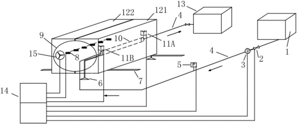
[0038] like figure 1 As shown, a kind of medium and high temperature solar heat collecting tube optical efficiency testing device proposed by the present invention is used to test the optical efficiency of medium and high temperature solar heat collecting tubes...


PUM


Abstract

The invention discloses an optical efficiency testing device for a medium-high temperature solar collector tube. The optical efficiency testing device is used for testing the optical efficiency of the medium-high temperature solar collector tube, and comprises a water supply tank, a housing and a water storage tank, wherein the housing is provided with a chamber of which the cross section is elliptical; the medium-high temperature solar collector tube, a solar simulative light source, a ventilation and heat dissipation device and a reflecting mirror surface are arranged in the elliptical chamber; the optical efficiency testing device further comprises a temperature acquisition unit and a flow acquisition unit, and also a control cabinet, wherein the temperature acquisition unit and the flow acquisition unit are arranged on a medium circulating pipeline and used for acquiring the temperature and the flow of a medium in the medium circulating pipeline; the control cabinet is used for providing power, data storage and equipment control for the testing device; the control cabinet is connected with the solar simulative light source, and controls the on and off of the solar simulative light source. The optical efficiency testing device for the medium-high temperature solar collector tube is capable of accurately testing the optical efficiency of the medium-high temperature solar collector tube, and has the advantages of stable light source, controllable irradiation power, controllable medium flow, accurate temperature measurement and easy operation.

Description

technical field [0001] The invention relates to the field of solar heat utilization, in particular to an optical efficiency device of a medium-high temperature solar heat collecting tube. Background technique [0002] Solar energy is the most important basic energy among all kinds of renewable energy. It has the advantages of abundant resources, inexhaustible, inexhaustible, and will not pollute the environment and destroy the ecological balance. Therefore, in today's world where fossil fuels are decreasing year by year and the international energy situation is becoming increasingly severe, the development and utilization of solar energy is one of the important ways to realize the diversification of energy supply and ensure energy security. The concentrator-type medium-high temperature solar collector tube can be applied in the field of industrial heating and power generation. It is an important development direction of the solar thermal industry in the future. Its performan...

Claims


Application Information

Patent Timeline
Patent Type & Authority Patents(China)
IPC IPC(8): F24J2/24G01M11/00F24S10/70
CPCY02E10/44
Inventor 雷东强李强都娜丽郝志永张峰章金国
Owner HIMIN SOLAR
Why Eureka
Try Eureka