
Load measuring device and measuring method thereof

A technology of load measurement and load, which is applied in the direction of measuring devices, measuring force, instruments, etc., can solve the problems of bulky, expensive, and limited range of load measuring devices, and achieve the effects of practicability, low cost, and easy movement

Inactive Publication Date: 2014-04-23
UNIV OF SHANGHAI FOR SCI & TECH
View PDF8 Cites 6 Cited by
  • Summary
  • Abstract
  • Description
  • Claims
  • Application Information

AI Technical Summary

Problems solved by technology

[0003] At present, in the actual engineering and production practice, there are not many load testing devices, and the measurement results are not ideal. The main problem is that the load measuring devices are often bulky, limited in range, fixed in the measuring place, and expensive. The result data in the reading process cannot record the entire measurement process of the load, only the static load can be measured, and the dynamic and periodic impact load cannot be measured in real time. For example, in textile machinery and printing machinery, periodic impact load There are great difficulties in the measurement of cyclic impact loads, and the measurement of cyclical impact loads is crucial in some fields, so a measuring device that can measure both static loads and dynamic cyclical loads is very important

Method used


Image

  • Load measuring device and measuring method thereof
  • Load measuring device and measuring method thereof
  • Load measuring device and measuring method thereof

Examples


Embodiment 1

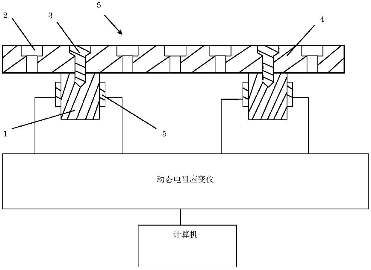
[0042] figure 1 is a schematic diagram of the cross-sectional structure of the load measuring device of the present invention in an embodiment.

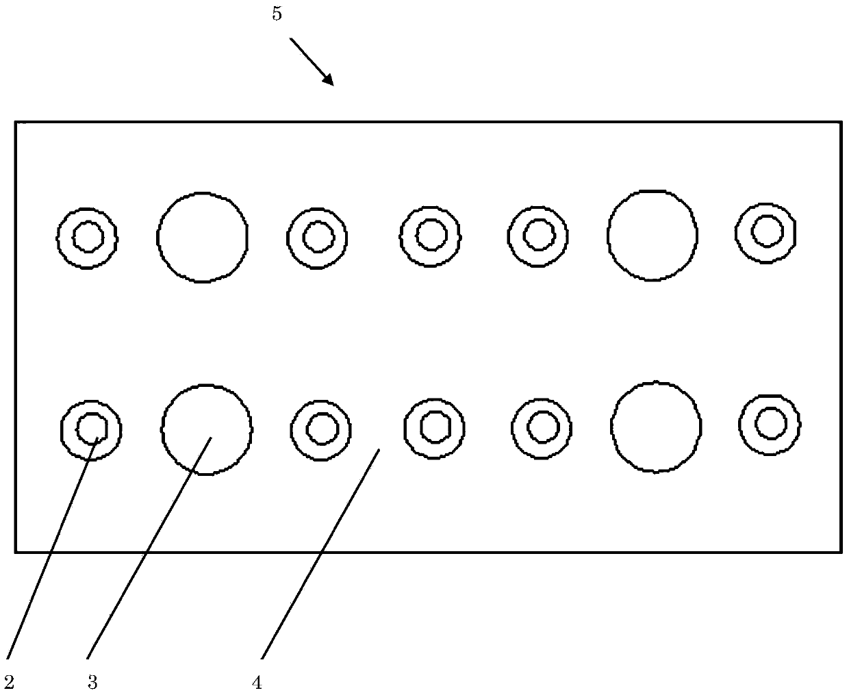
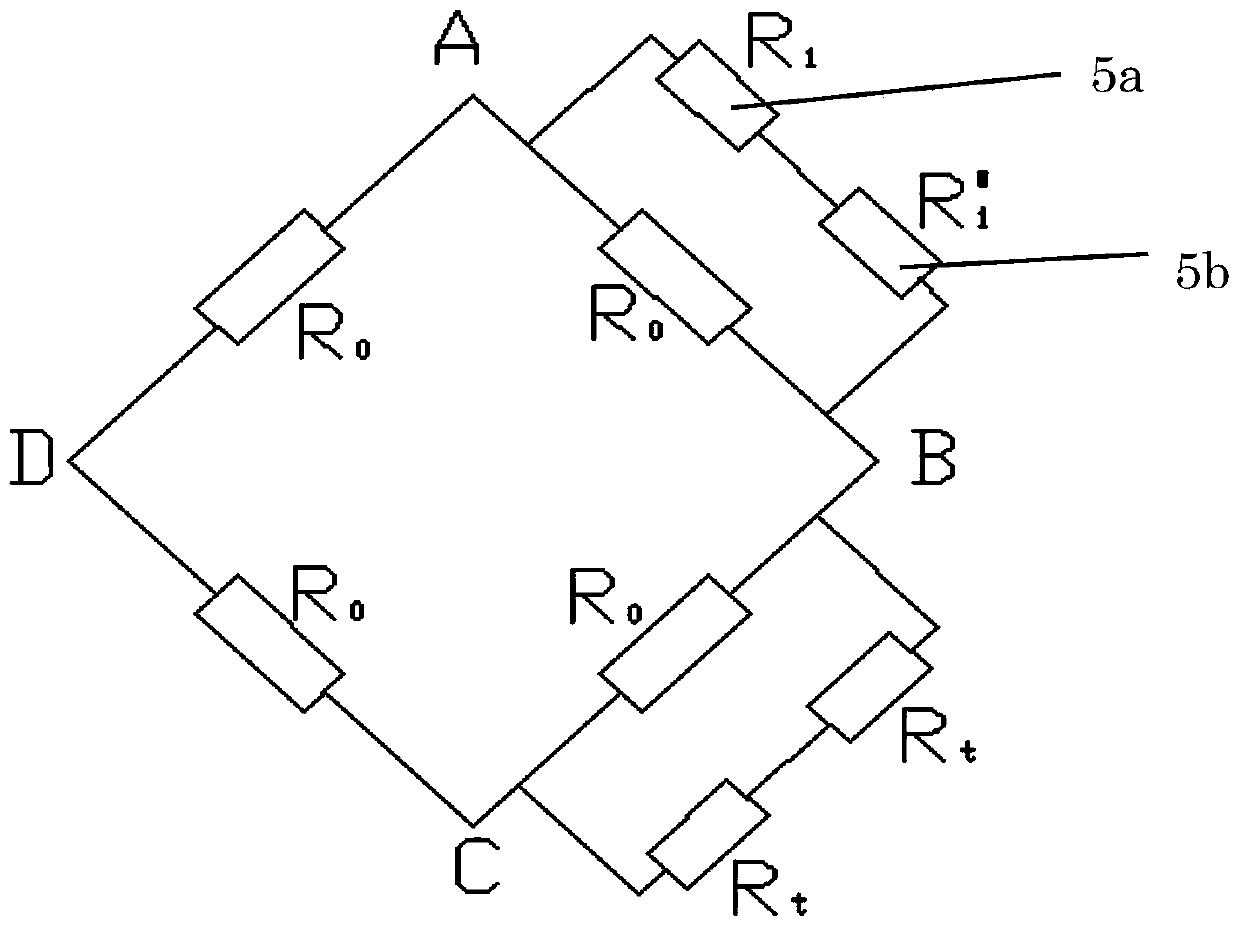
[0043] Such as figure 1 As shown, the supporting part of the load measuring device 5 includes a bearing plate 4 and four bearing columns 1. The ratio of the height to the diameter of the bearing columns 1 is 1.5:1, and the material used is a metal material with good elasticity. The level of the whole device is such that each bearing column 1 is subjected to an equal load, wherein the symmetrical position on each bearing column 1 is polished and used to attach two series resistance strain gauges 5a and 5b, and one bearing column 1 The two resistance strain gauges 5a and 5b are connected to the dynamic resistance strain gauge of the measuring section. The dynamic resistance strain gauge is connected to the computer of the data processing department.

[0044] The bearing plate 4 is connected with the bearing columns 1 by screws 3. Si...

Embodiment 2

[0066] This embodiment provides a method for measuring load using the above-mentioned load measuring device, and the specific steps are as follows:

[0067] Step 1: First select the size of the load-bearing column so that the ratio of height h to diameter D is 1.5, measure the cross-sectional area of ​​the load-bearing column to meet the requirements of GB / T7314-2005 metal material room temperature compression test method, and then load the column that meets the size requirements Grind the front and back symmetrical parts on the cylinder surface in the middle of the column, and paste the resistance strain gauge.

[0068] Step 2: Pre-compress the load-bearing columns with the strain gauges pasted on them within the elastic range with as large and the same preload as possible, and measure the elastic modulus E of all the load-bearing columns;

[0069] Step 3: Connect the bearing column with the bearing plate with screws, and at the same time connect the two resistance strain gau...


PUM


Abstract

The invention provides a load measuring device and a measuring method thereof. The load measuring device is characterized by being provided with a supporting part, a measuring part connected with the supporting part, and a data processing part connected with the measuring part, wherein the supporting part comprises a bearing plate and a bearing post; the bearing post is connected to the bottom of the bearing plate; the measuring part comprises a resistance strain gauge and a resistance strain indicator connected with the resistance strain gauge; the resistance strain gauge is connected to the bearing post; the data processing part is connected with the resistance strain indicator to receive a strain value in order to obtain a strain curve. The measuring method comprises the following steps: selecting the proper bearing post, and sticking the resistance strain gauge to the bearing post; measuring the elastic modulus of the bearing post to which the resistance strain gauge is attached, connecting the resistance strain gauge to the resistance strain indicator, loading a load to be measured to the bearing plate, measuring a strain value by using the resistance strain indicator to obtain the strain curve, and calculating to obtain the load. By adopting the structure, static loads and periodic impact loads can be measured efficiently and rapidly, the cost is low, and high practicability is achieved.

Description

technical field [0001] The invention relates to a load measuring device and a measuring method thereof. Background technique [0002] Load measuring devices are often used in construction machinery, transportation, textile machinery, printing machinery and other industries to measure the weight of goods or check the pressure value of mechanical equipment, detect the static load and various dynamic impact loads imposed by large equipment, so as to monitor heavy cargo Whether it is within the safe range, whether the impact load of the equipment meets the set requirements, ensures the safety of engineering transportation, and improves the service life of large-scale loading equipment. [0003] At present, in the actual engineering and production practice, there are not many load testing devices, and the measurement results are not ideal. The main problem is that the load measuring devices are often bulky, limited in range, fixed in the measuring place, and expensive. The resul...

Claims


Application Information

Patent Timeline
IPC IPC(8): G01L1/22
Inventor 倪维宇姚胜卫张坤张横张林森侯丽园
Owner UNIV OF SHANGHAI FOR SCI & TECH
Learn More