All-directional high-speed laser bar code scanning device

A laser barcode and scanning device technology, applied in the field of barcode scanning, can solve the problems of affecting the barcode recognition effect and convenience of use, slow scanning speed of laser light source, small scannable range, etc., to achieve good barcode recognition effect, fast scanning speed, Wide range of scan effects

Active Publication Date: 2014-04-23
SUNLUX IOT TECH GUANGDONG
View PDF6 Cites 18 Cited by
  • Summary
  • Abstract
  • Description
  • Claims
  • Application Information

AI Technical Summary

Problems solved by technology

[0007] Although the above technical solution increases the number of laser scanning lines and improves the barcode recognition effect, it only repeatedly increases the number of existing scanning lines in the original scanning line optical network, so it can only form scanning line light within a limited angle. Network, that is, the scanning angle covered by the scanning line optical network still fails to achieve 360-degree coverage, and the scanable range is small, such as figure 2 Below the scanning line optical network shown is the scanning blind area. The barcode to be tested still needs to be placed in the scanning line optical network at a certain angle and in the correct position to align with the scanning line to be correctly recognized, which affects the barcode recognition effect. and ease of use, and the defect that the scanning speed of a single laser light source is slow has not been resolved

Method used


Image

  • All-directional high-speed laser bar code scanning device
  • All-directional high-speed laser bar code scanning device
  • All-directional high-speed laser bar code scanning device

Examples


Embodiment Construction

[0040] The following will clearly and completely describe the technical solutions in the embodiments of the present invention with reference to the drawings in the embodiments of the present invention.

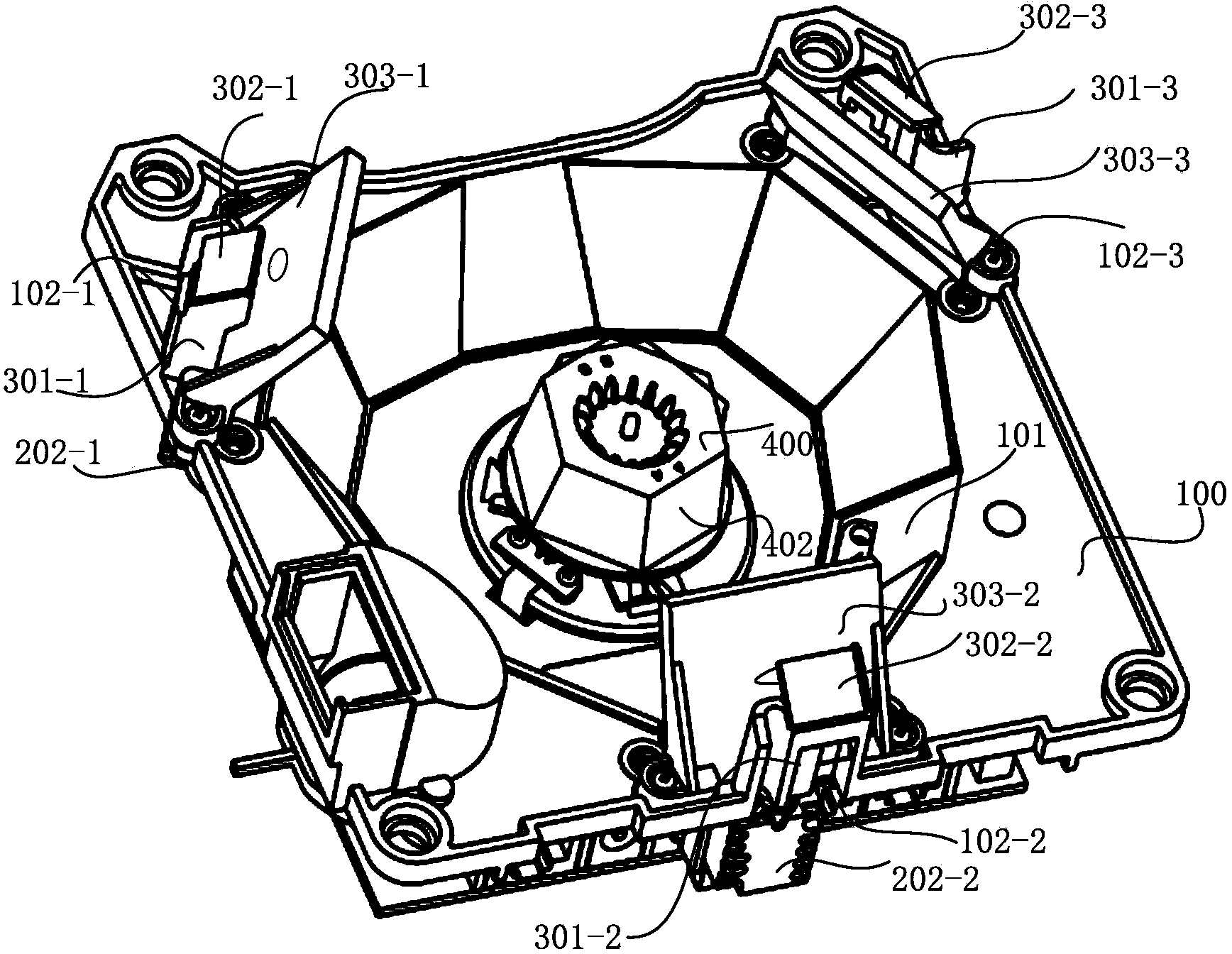
[0041] Combine below Figure 3 ~ Figure 11 , the structure of the omnidirectional high-speed laser barcode scanning device provided by the present invention will be described in detail.

[0042] see image 3 , is a three-dimensional schematic diagram of an embodiment of the omnidirectional high-speed laser barcode scanning device provided by the present invention; Figure 4 is the invention image 3 The front view of the omni-directional high-speed laser barcode scanning device provided; Figure 5 is the invention image 3 Partial structural cross-sectional view of the omni-directional high-speed laser barcode scanning device provided.

[0043] In this embodiment, preferably, the barcode scanning device is used to scan and recognize one-dimensional barcodes and / or two-dim...


PUM


Abstract

The invention discloses an all-directional high-speed laser bar code scanning device. The device comprises a base shell, wherein a groove is formed in the middle of the base shell; three light source open grooves are formed in the periphery of the base shell; the included angle between every two adjacent light source open grooves is 120 degrees; three laser diodes are correspondingly fixed in the light source open grooves; three reflecting mirror brackets are in one-to-one correspondence to the light source open grooves; each reflecting mirror bracket is provided with an emitted light reflecting mirror and a received light reflecting mirror; an opening is formed in the middle of the received light reflecting mirror; a rotary reflecting mirror group is arranged at the central position of the groove; the rotary reflecting mirror group comprises a rotary motor and a plurality of reflecting mirrors arranged on the side surfaces of the rotary motor; an annular column reflecting mirror group is arranged on the side surface of the boundary of the groove; three light receiving open grooves are formed below the rotary reflecting mirror group, wherein the included angle between every two adjacent light receiving open grooves is 120 degrees; a photosensitive receiving tube is arranged on each light receiving open groove. The all-directional high-speed laser bar code scanning device provided by the invention has the advantages of wide scanning range, high scanning speed, large line number, good bar code identification effect and the like.

Description

technical field [0001] The invention relates to the technical field of barcode scanning, in particular to an omnidirectional high-speed laser barcode scanning device. Background technique [0002] Barcode scanning device, also known as barcode reader, barcode scanning gun, barcode scanner, barcode scanning gun, etc., is a device that uses optical principles to decode the information contained in the barcode and then transmit it to the computer through a data line or wirelessly. and other devices. The barcode scanning device has accurate recognition, fast data input speed, simple equipment and low cost, and is widely used in commercial POS (Point Of Sale, sales terminal) cash register systems, supermarkets, express delivery, warehousing, logistics, books, medicine and other fields . [0003] According to different light sources, barcode scanning devices can be divided into rainbow barcode scanners and laser (Laser, transliterated as laser) barcode scanners. Hongguang barco...

Claims


Application Information

Patent Timeline
Patent Type & Authority Applications(China)
IPC IPC(8): G06K7/10G02B26/12
CPCG06K7/10831
Inventor 徐朝荣
Owner SUNLUX IOT TECH GUANGDONG
Why Eureka
Try Eureka