Permanent-magnet synchronous motor, stator and rotor
A permanent magnet synchronous motor and rotor technology, used in synchronous motors with stationary armatures and rotating magnets, synchronous machine parts, etc., to eliminate cogging torque, eliminate additional pulsating axial force, reduce noise and vibration Effect
- Summary
- Abstract
- Description
- Claims
- Application Information
AI Technical Summary
Problems solved by technology
Method used
Image
Examples
Embodiment 1
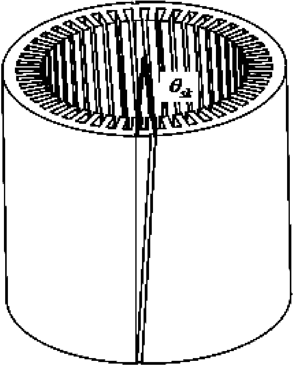
[0047] Permanent magnet synchronous motor, including stator and rotor, the stator and rotor are coaxial;
[0048] In the stator, the tooth grooves are V-shaped oblique grooves;
[0049] said rotor, the poles of which are distributed in a direction parallel to the axis; or
[0050] In the stator, the tooth slots are distributed along a direction parallel to the axis;
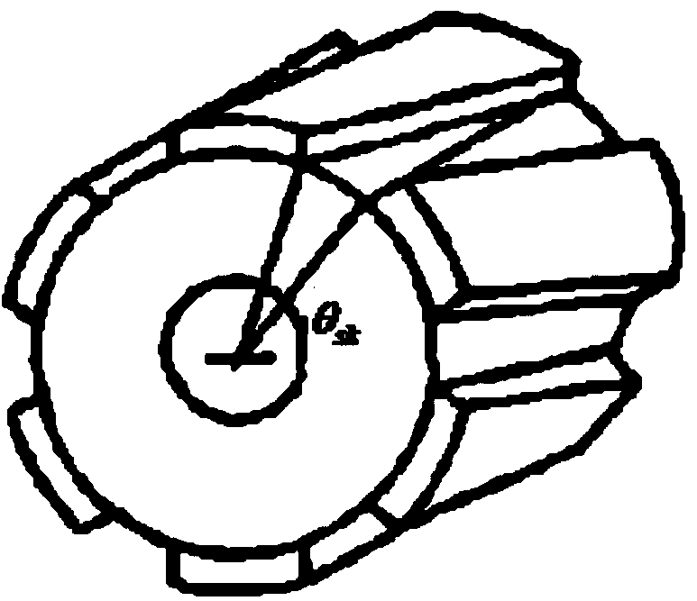
[0051] The magnetic pole of the rotor has a V-shaped oblique pole.
[0052] Preferably, in the V-shaped chute or V-shaped oblique pole, the torsional inclination angle of the first half of the axis to one side is equal to the torsional inclination angle of the second half of the axis to the opposite side, and the axes of the first half and the second half are equal distance.
[0053] The permanent magnet synchronous motor of embodiment one, as Figure 4 As shown in , the stator with V-shaped inclined groove or the rotor with V-shaped oblique poles is twisted to one side in the first half of the axis by the an...
Embodiment 2
[0064] Based on the permanent magnet synchronous motor of Embodiment 1, the torsional inclination angle θ of the V-shaped chute or V-shaped oblique pole sk for:
[0065] (Formula 8)
[0066] In the formula, N c It is the least common multiple of the number of stator teeth Z and the number of rotor poles 2p, and i is a positive integer. However, choosing a larger i value may cause a sharp decline in the peak performance of the motor, and it is recommended that i=1.
[0067] For example, a permanent magnet synchronous motor plans to use a V-shaped skewed stator scheme, the number of stator teeth Z=24, and the number of rotor poles 2p=16, then its inclination angle θ sk for:
[0068] i can be 1, 2, 3, 4, 5, 6..., θ sk It can be 7.5°, 15°, 22.5°, 30°, 37.5°, 45°... .
Embodiment 3
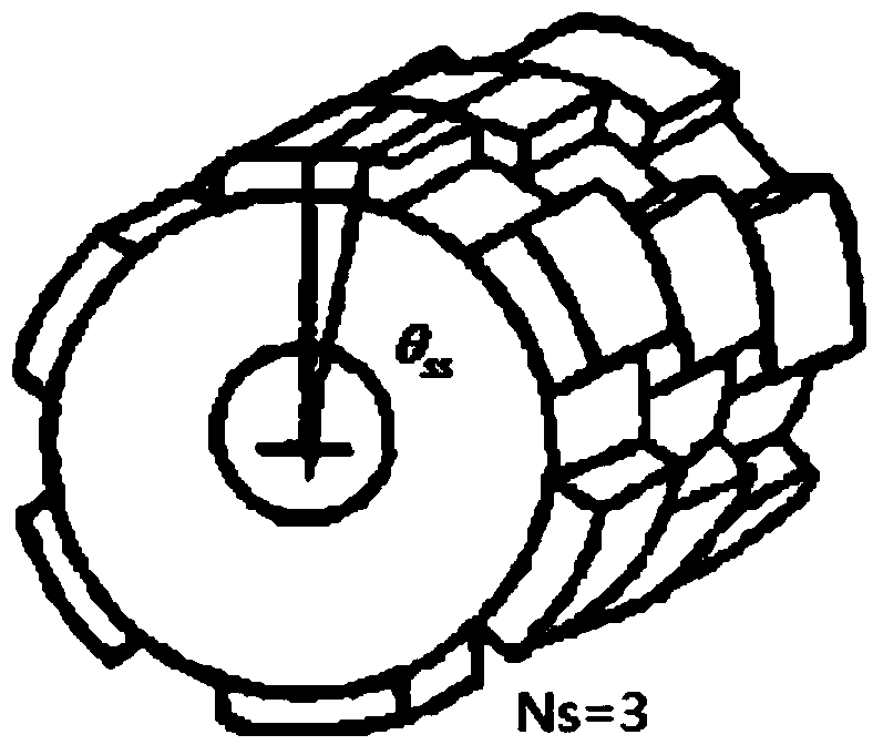
[0070] Based on the permanent magnet synchronous motor of embodiment one, such as Image 6 , Figure 7 As shown, the V-shaped skew pole of the rotor is represented by N s segment composition, N s is an integer greater than or equal to 3.
[0071] In the permanent magnet synchronous motor of the third embodiment, the oblique poles of the rotor are dislocated in V-shaped segments, which can imitate the V-shaped oblique poles. In order to ensure the complete offset of the additional axial force, the segment number N of the rotor s It should be chosen as an even number as much as possible. In order to ensure the meaning of segmentation, when Ns is an even number, Ns>=3 should be selected, such as Image 6 As shown, the skew poles of the rotor should be misaligned by an angle θ ss for:
[0072] (Formula 9)
[0073] However, choosing a larger j value may cause a sharp drop in the peak performance of the motor, and j=1 is recommended.
[0074] For example, a permanent m...
PUM
 Abstract
Description
Claims
Application Information
 - R&D
- Intellectual Property
- Life Sciences
- Materials
- Tech Scout
- Unparalleled Data Quality
- Higher Quality Content
- 60% Fewer Hallucinations
Browse by: Latest US Patents, China's latest patents, Technical Efficacy Thesaurus, Application Domain, Technology Topic, Popular Technical Reports.
© 2025 PatSnap. All rights reserved.Legal|Privacy policy|Modern Slavery Act Transparency Statement|Sitemap|About US| Contact US: help@patsnap.com


