Loudspeaker reliability test device

A test device and speaker technology, applied in electrical components and other directions, can solve the problems of high cost, easy failure, large space occupation, etc., to achieve the effect of improving service life, avoiding line failure, and occupying small space

Active Publication Date: 2014-04-23
GOERTEK INC
View PDF4 Cites 8 Cited by
  • Summary
  • Abstract
  • Description
  • Claims
  • Application Information

AI Technical Summary

Problems solved by technology

[0002] Existing loudspeaker reliability testing devices either use embedded processors, which are mostly not friendly enough for human-computer interaction and are inconvenient to operate; or use external PCs, which take up a lot of space and increase the cost of the user
Usually, the audio power amplifier in the device adopts an external power amplifier or power amplifier card. Each power amplifier needs wiring, including power lines, signal input lines, signal output lines, etc. When there are many channels, the number of wiring is as many as dozens or even up to Hundreds of pieces make the whole device too messy, prone to failure and difficult to maintain
And the existing loudspeaker reliability testing device mostly adopts the relay to control the power amplifier in the control mode of the on-off signal. Since the relay has a limited lifespan, if the on-off switch is used for a long time, the life of the instrument is shortened, and the protection of the power amplifier and the speaker under test , either without protection, or adding a special signal source controller, the design is cumbersome
In addition, existing loudspeaker reliability testing devices cannot observe real-time waveforms and frequency spectra. If observation is required, an oscilloscope must be used to view it. The operation is cumbersome and the cost is high.

Method used


Image

  • Loudspeaker reliability test device
  • Loudspeaker reliability test device

Examples


Embodiment Construction

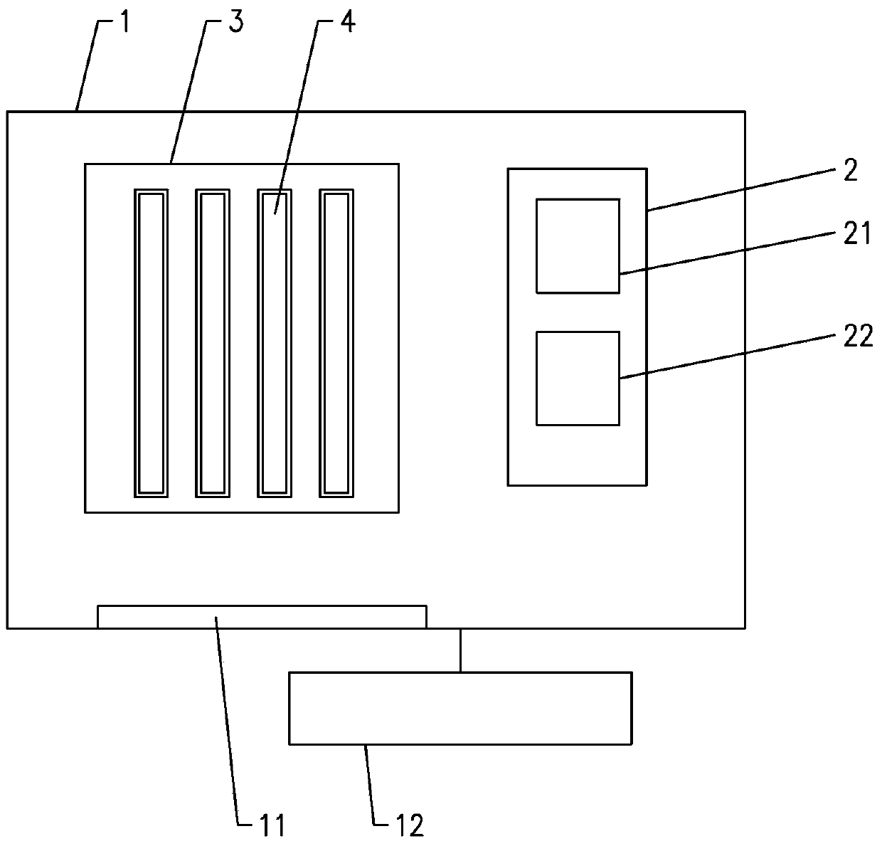
[0020] Such as figure 1 and figure 2 Commonly shown, a loudspeaker reliability testing device. This loudspeaker reliability testing device comprises cabinet 1, is provided with display 11 on cabinet 1 panel, for the convenience of operation, is also provided with the keyboard 12 that is connected with cabinet 1, is provided with computer system 2 in cabinet 1, cabinet among the present embodiment 1 and the computer system 2 directly use industrial computers, and all functional components are placed in the chassis 1, which realizes the miniaturization of the equipment and occupies a small space.

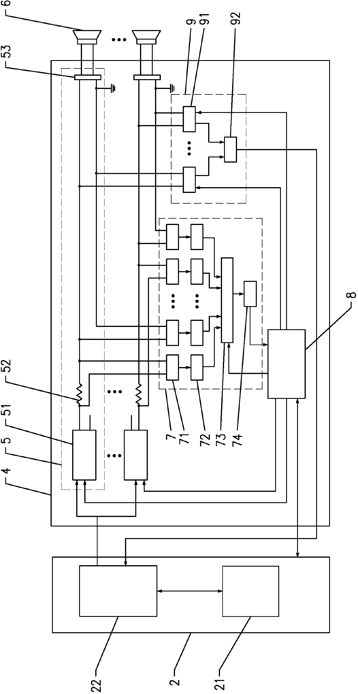
[0021] The computer system 2 is provided with a LabView processing module 21 and an audio card 22. The audio card 22 adopts DELTA66 or MAYA44, and the LabView processing module 21 can edit, store and play test signals in the form of multimedia files, which is convenient and flexible. The interface is realized with convenient operation and clear information.

[0022] Also be provid...


PUM


Abstract

The invention discloses a loudspeaker reliability test device comprising a machine box which is internally provided with a computer system. The computer system is provided with a LabView processing module and an audio card. The loudspeaker reliability test device also comprises a test card which is arranged in the machine box and connected with the computer system. The test card is provided with multipath of test channels which are formed by audio power amplifier chips, sampling resistors and loudspeaker connecting terminals in a series-connection way. The input end of each audio power amplifier chip is connected with the output end of the audio card. The test card is also provided with a voltage and current acquisition module and a single-chip microcomputer. Two ends of each sampling resistor and each loudspeaker connecting terminal are connected with the input end of the voltage and current acquisition module. The output end of the voltage and current acquisition module is connected with an I / O of the single-chip microcomputer. The I / O of the single-chip microcomputer is also connected with a mute pin of each audio power amplifier chip. A serial port of the single-chip microcomputer is connected with the computer system. The loudspeaker reliability test device is concise in structure, convenient to operate and maintain, stable and reliable and long in the service life.

Description

technical field [0001] The invention relates to a loudspeaker reliability testing device. Background technique [0002] Existing loudspeaker reliability testing devices either use an embedded processor, which is mostly not friendly enough for human-computer interaction and is inconvenient to operate; or use an external PC, which takes up a lot of space and increases the cost of the user. Usually, the audio power amplifier in the device adopts an external power amplifier or power amplifier card. Each power amplifier needs wiring, including power lines, signal input lines, signal output lines, etc. When there are many channels, the number of wiring is as many as dozens or even up to Hundreds of pieces make the whole device too messy, easy to break down, and difficult to maintain. And the existing loudspeaker reliability testing device mostly adopts the relay to control the power amplifier in the control mode of the on-off signal. Since the relay has a limited lifespan, if the...

Claims


Application Information

Patent Timeline
Patent Type & Authority Applications(China)
IPC IPC(8): H04R29/00
Inventor 陈军生李宁谭礼君
Owner GOERTEK INC
Why Eureka
Try Eureka