Thermal deposition apparatus

A thermal evaporation and evaporation technology, which is used in vacuum evaporation coating, sputtering coating, ion implantation coating and other directions, can solve the problems of large evaporation deviation, difficulty in uniform evaporation, and reduced evaporation quality, etc. The effect of reducing impurity content, increasing use efficiency and improving evaporation quality

Inactive Publication Date: 2014-04-23
MMT CO LTD
View PDF5 Cites 0 Cited by
  • Summary
  • Abstract
  • Description
  • Claims
  • Application Information

AI Technical Summary

Problems solved by technology

[0006] During the described process, not only will the efficiency of the evaporation material be reduced, but it may also react with impurities, thereby reducing the overall quality of the evaporation
In addition, the disadvantage is that due to the heater structure of the conventional heater, it is difficult to uniformly vaporize the top and bottom of the device surface, especially the vapor deposition deviation of the boat-shaped heater is very large

Method used


Image

  • Thermal deposition apparatus
  • Thermal deposition apparatus
  • Thermal deposition apparatus

Examples


Embodiment Construction

[0021] Hereinafter, the preferred embodiments according to the present invention will be described in detail with reference to the drawings. Prior to this, the terms or words used in this specification and claims are not limitedly interpreted as general or prior meanings, but should be interpreted as meanings and concepts consistent with the technical idea of ​​the present invention.

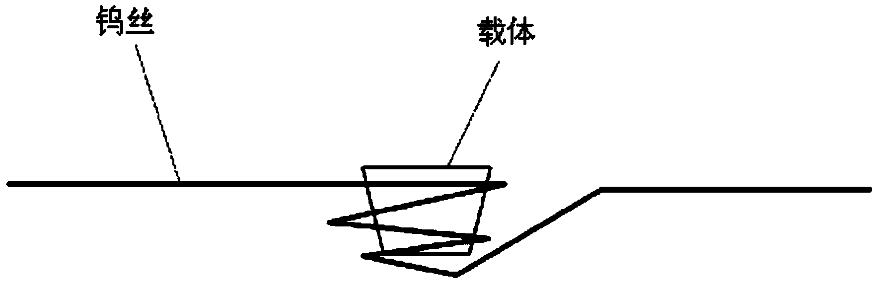
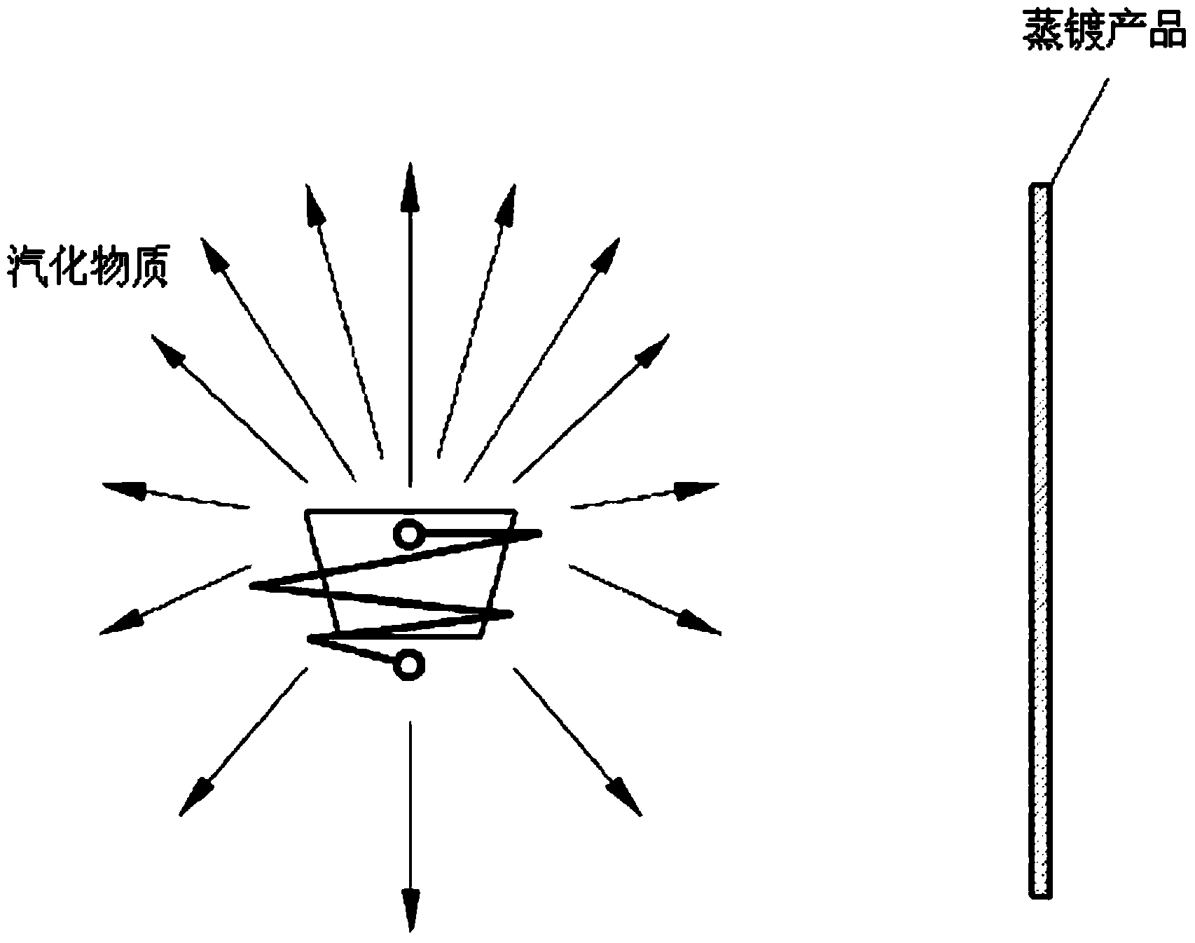
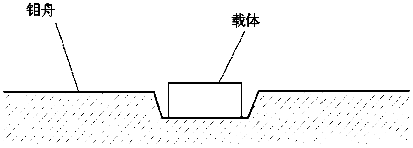
[0022] The present invention relates to a thermal vapor deposition device, which includes: a carrier, which contains the existing vapor deposition material; a heater, which heats the carrier containing the vapor deposition material; a jig, which is used to carry equipment to form It is movable in front of the carrier. Wherein, the heater is a plate-shaped metal heater, which is arranged parallel to the idle axis of the equipment, and the carrier is located in front of the plate-shaped metal heater.

[0023] In other words, as shown in Figures 3 to 5, the thermal vapor deposition device of the presen...


PUM

PropertyMeasurementUnit
porosityaaaaaaaaaa

Abstract

The present invention relates to a thermal deposition apparatus that reduces the rate of deposition variation using a plate-shaped metal heater instead of an existing tungsten filament or molybdenum boat, and more particularly, to a thermal deposition apparatus which uses a plate-shaped metal heater installed parallel to a processing axis of a substrate, and which uses a carrier positioned on the front surface of the plate-shaped metal heater. By using the thermal deposition apparatus of the present invention, the efficiency of use of deposited materials can be improved, and the deposited materials can be deposited on the substrate in a uniform and reproducible manner.

Description

Technical field [0001] The present invention relates to a thermal evaporation device, which replaces the existing tungsten filament or molybdenum boat, and uses a plate-shaped metal heater to reduce the evaporation deviation rate, and more specifically to the use of plate-shaped The metal heater and the carrier thermal evaporation device, the plate-shaped metal heater is set parallel to the idle shaft of the equipment, and the carrier is located on the front of the plate-shaped metal heater. By using the thermal vapor deposition device of the present invention, the use efficiency of vapor deposition materials can be increased, and the vapor deposition materials can be uniformly and reproducibly vapor-deposited on the equipment. Background technique [0002] In the case of smartphones, because the front tempered glass is all used as an input tool, the front of the tempered glass has a fingerprint-resistant surface, and with the increase in demand for smartphones, a method for mass...

Claims


Application Information

Patent Timeline
Patent Type & Authority Applications(China)
IPC IPC(8): C23C14/24C23C14/06
CPCC23C14/26C23C14/243C23C14/06C23C14/24
Inventor 金润泽林朝燮
Owner MMT CO LTD
Why Eureka
Try Eureka