
Chain drive device for camshaft drive

A technology of camshaft and chain transmission, applied in the direction of transmission, machine/engine, belt/chain/gear, etc., can solve the problems of difficult engine layout, poor lubrication, heavy rollers, etc., to achieve engine layout and prevent roller lubrication Defective, movement resistance reduction effect

Inactive Publication Date: 2014-04-23
NTN CORP
View PDF5 Cites 1 Cited by
  • Summary
  • Abstract
  • Description
  • Claims
  • Application Information

AI Technical Summary

Problems solved by technology

[0008] However, in the chain transmission device for driving a camshaft described in the aforementioned Patent Document 1, there is no description of the relative size relationship between the drive sprocket and the roller that guides the movement of the chain.
Among them, if the ratio of the diameter of the pitch circle of the drive sprocket to the outer diameter of the roller that guides the movement of the chain is too large, when the engine rotates at high speed, the roller rotates at a high speed and poor lubrication occurs between the roller and the roller shaft.
In addition, if the ratio of the pitch circle diameter of the drive sprocket to the outer diameter of the roller is reduced, the roller becomes heavier, and the layout of the engine becomes difficult due to the increase in the outer diameter of the roller.

Method used


Image

  • Chain drive device for camshaft drive
  • Chain drive device for camshaft drive
  • Chain drive device for camshaft drive

Examples


Embodiment Construction

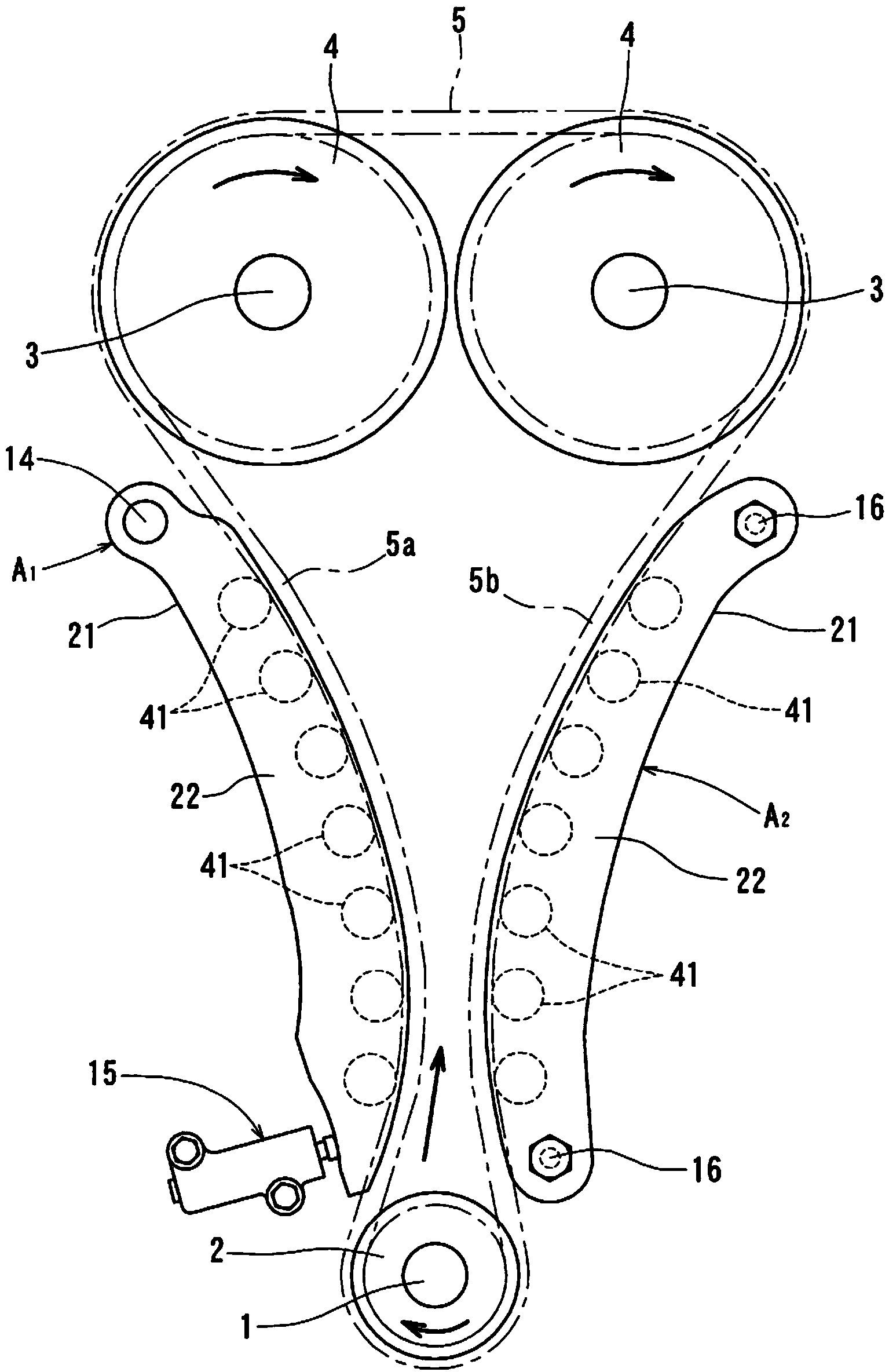
[0025] Hereinafter, embodiments of the present invention will be described based on the drawings. figure 1 Represents a chain transmission device for driving a camshaft. A timing chain is spanned between a driving sprocket 2 mounted on the shaft end of the crankshaft 1 and a driven sprocket 4 mounted on the shaft ends of two camshafts 3 respectively. 5.

[0026] The timing chain 5 can be a roller chain or a silent chain.

[0027] Crankshaft 1 direction figure 1 Rotate in the direction indicated by the arrow. By the rotation of the crankshaft 1, the timing chain 5 moves in the direction indicated by the arrow in the figure, so that the part from the driving sprocket 2 to the driven sprocket 4 on the left side in the figure becomes the slack side, so that The portion from the other driven sprocket 4 to the drive sprocket 2 is the tension side, and a chain guide A is provided on one side of the slack side chain 5a. 1 .

[0028] Chain guide A 1 Extending longer along the mov...


PUM


Abstract

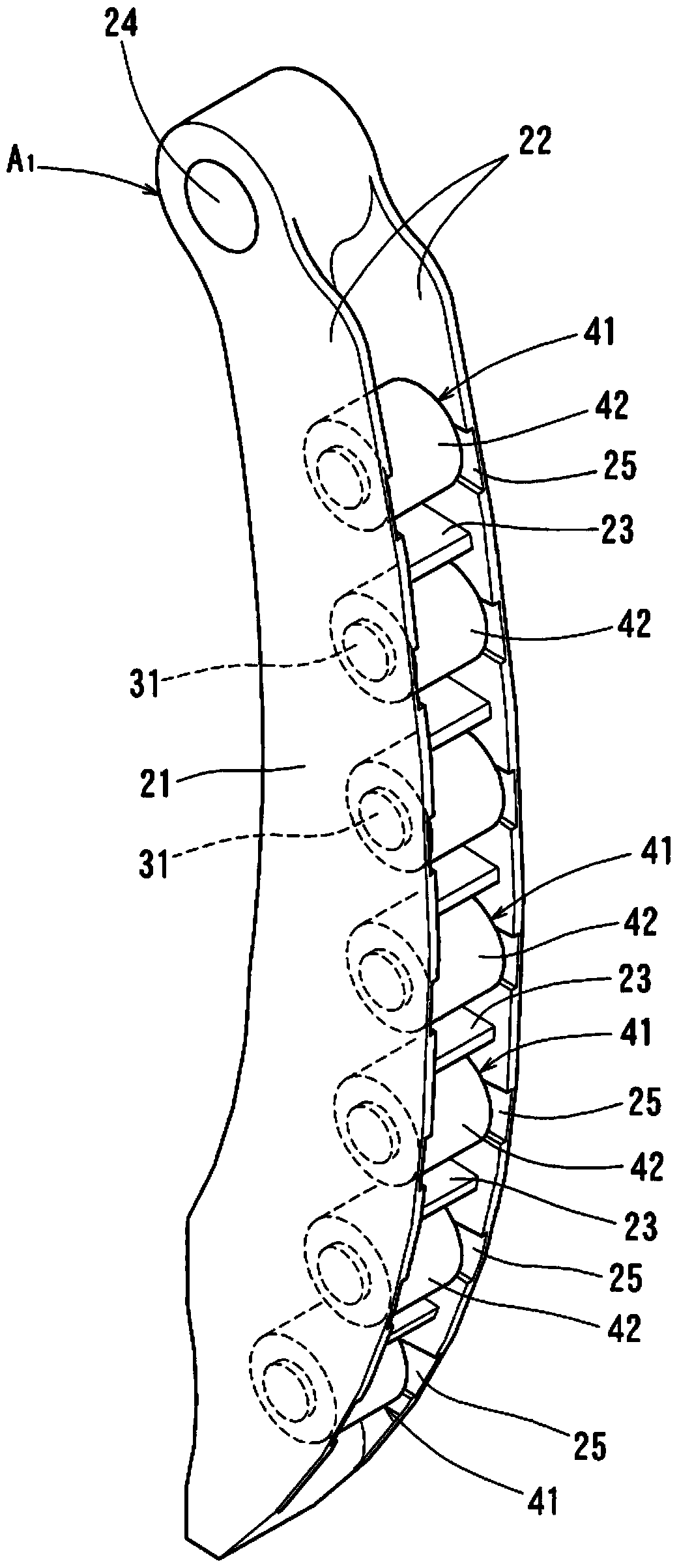
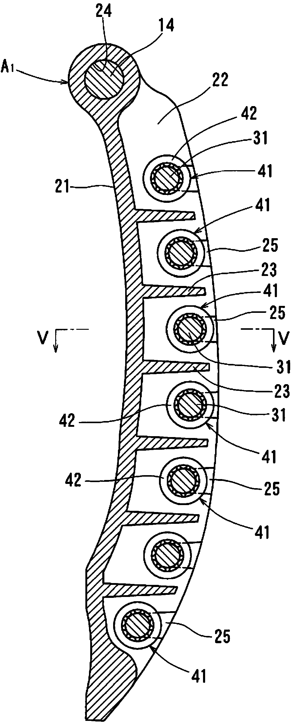
In a chain drive device for a camshaft drive, a timing chain (5) is run between a drive sprocket (2) attached to a crankshaft (1) and a driven sprocket (4) attached to a camshaft (3), and a chain guide (A1) that has a plurality of rotatable rollers (41) that guide the movement of the timing chain (5) is pivotably provided on one side of the slack side of the timing chain (5). An accommodating force from a chain tensioner is applied to the pivoting end of the chain guide, pushing the rollers (41) up against the timing chain (5). The ratio (D1:D2) between the pitch circle diameter (D1) of the drive sprocket (2) and the outer diameter (D2) of the rollers (41) is between 5:3 and 5:1, preventing the chain-guiding rollers (41) from suffering lubrication problems and simplifying the engine layout.

Description

technical field [0001] The invention relates to a chain drive for camshaft drive. Background technique [0002] In a camshaft driving chain drive in which a timing chain is bridged between a drive sprocket mounted on the crankshaft and a driven sprocket mounted on the camshaft, a swingable chain is provided on the loose side of the timing chain Apply the adjustment force of the chain tensioner to the swing side end of the chain guide to tighten the timing chain, thereby preventing the chain from loosening and shaking. [0003] In addition, a chain guide is provided on the tension side chain of the timing chain as a fixed arrangement, and movement of the timing chain is guided by the fixed chain guide, thereby suppressing chattering of the chain. [0004] Among them, as a chain guide for adjusting the tension of the timing chain and for guiding movement, there is known a chain guide in the form of guiding the timing chain in a plane by sliding contact, but there is a large m...

Claims


Application Information

Patent Timeline
Patent Type & Authority Applications(China)
IPC IPC(8): F16H7/08F02B67/06F16H7/18F16H7/20
CPCF16H2007/0865F16H7/08F16H7/18F16H2007/0872F16H7/20F02B67/06F16H7/06F16H7/1281F16H2007/0893
Inventor 加藤晃央大石真司
Owner NTN CORP
Learn More