Automatic multi-station catalyst coating device

An automatic coating and catalyst technology, applied to the surface coating liquid device, coating, transportation and packaging, etc., can solve the problems of uneven distribution of slurry, low processing efficiency, complex production line devices, etc. Good stability, high machining precision and high degree of automation

Active Publication Date: 2014-04-30
CHANGZHOU FANQUN DRY EQUIP CO LTD
View PDF5 Cites 18 Cited by
  • Summary
  • Abstract
  • Description
  • Claims
  • Application Information

AI Technical Summary

Problems solved by technology

[0002] The existing catalyst coating process needs multiple processing processes such as weighing, slurry coating, spraying and drying, and the process flow is very cumbersome
In some existing manufacturers, when coating the carrier, the processes of weighing, slurrying, spraying and drying are all processed separately. The carrier needs to be weighed first, and then manually transported to the slurrying station. After the slurry is coated, it is manually transported to the spraying station, and then transported to the drying station after spraying. , or due to uneven placement of the carrier during the handling process, the slurry is unevenly distributed on the carrier, which greatly affects the quality of the product
[0003] Although some manufacturers have also begun to use production lines to optimize the catalyst coating process, generally the carrier is automatically transported to each processing station through a conveyor belt. However, this type of production line device is relatively complicated, bulky, and requires a large footprint Processing efficiency is still low

Method used


Image

  • Automatic multi-station catalyst coating device
  • Automatic multi-station catalyst coating device
  • Automatic multi-station catalyst coating device

Examples


Embodiment Construction

[0028] The present invention is described in further detail now in conjunction with accompanying drawing. These drawings are all simplified schematic diagrams, which only illustrate the basic structure of the present invention in a schematic manner, so they only show the configurations related to the present invention.

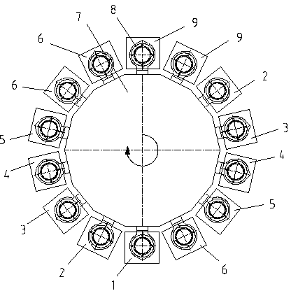
[0029] Such asfigure 1 As shown, a multi-station catalyst automatic coating device, including

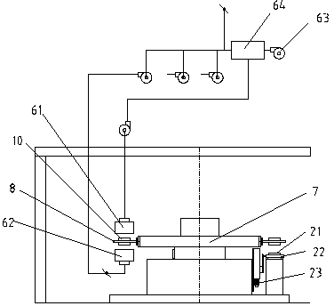
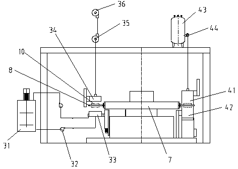
[0030] A conveying device for conveying the carrier 10 and detecting the position of the carrier 10, the conveying device includes a stepping carrier on-line chain plate conveying line, a stepping carrier off-line chain plate conveying line and a positioning detection mechanism, the positioning detection mechanism They are respectively installed on the chain plate conveyor line on the stepping carrier line and the chain plate conveyor line on the stepping carrier off line;

[0031] An on-line and off-line carrier robot 1 for grabbing and transferring the carrier 10...


PUM


Abstract

The invention relates to an automatic multi-station catalyst coating device. The device comprises a conveying device for conveying a carrier and positioning and detecting the carrier, an upper line-lower line carrier robot for catching and conveying the carrier, a transmission device for receiving the carrier from the upper line-lower line carrier robot and transmitting the carrier to different processing stations, and a coating station for coating the carrier, wherein the coating station comprises a primary coating station, a secondary coating station and a cooling device. The transmission device is tightly cooperated with each coating device, so that the automatic degree is high, the mechanical process precision is high, the stability of the whole device is good, and the quality of the produced products is good. The coating device has an open type operation window, a carrier clamp can be exchanged, so as to achieve multiple kinds of coating and secondary coating, so that the automatic multi-station catalyst coating device is multifunctional, and has wide application range.

Description

technical field [0001] The invention relates to the field of catalyst coating production, in particular to a multi-station catalyst automatic coating device. Background technique [0002] The existing catalyst coating process requires multiple processes such as weighing, slurry coating, spraying and drying, and the process flow is very cumbersome. In some existing manufacturers, when coating the carrier, the processes of weighing, slurrying, spraying and drying are all processed separately. The carrier needs to be weighed first, and then manually transported to the slurrying station. After the slurry is coated, it is manually transported to the spraying station, and then transported to the drying station after spraying. , or the slurry is unevenly distributed on the carrier due to the uneven placement of the carrier during the handling process, which greatly affects the quality of the product. [0003] Although some manufacturers have also begun to use production lines to ...

Claims


Application Information

Patent Timeline
Patent Type & Authority Applications(China)
IPC IPC(8): B05C9/06B05C11/10B05C13/02B05D3/02B65G25/02
Inventor 王成轩范炳洪姚义峰
Owner CHANGZHOU FANQUN DRY EQUIP CO LTD
Why Eureka
Try Eureka