a flattening roller

A technology for flattening rollers and mandrels, applied in the field of machinery, can solve the problems of inconvenient maintenance and replacement of parts, wrinkles of plastic films, poor flattening effect, etc., and achieves convenient processing, consistent friction, and good flattening effect. Effect

Inactive Publication Date: 2016-08-31
郑州华翔电子信息技术有限公司
View PDF6 Cites 0 Cited by
  • Summary
  • Abstract
  • Description
  • Claims
  • Application Information

AI Technical Summary

Problems solved by technology

[0003] The problems of the flattening roller with the above structure are: 1. The plastic film is flattened solely through the slip between the roller and the roller core. The flattening effect of this method is not good, and the plastic film passing through the flattening roller may still have wrinkles.
2. The structure of another type of flattening roller for compound machines is not suitable for flattening plastic films, and the flattening roller is processed by machine tools, which has high processing requirements and is inconvenient for maintenance and replacement of parts

Method used


Image

  • a flattening roller
  • a flattening roller
  • a flattening roller

Examples


Embodiment 1

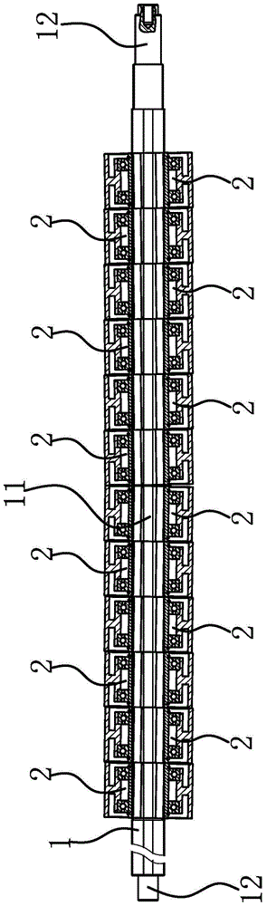
[0029] The flattening roller includes a mandrel 1 and a flattening unit 2 .

[0030] Specifically, as figure 1 As shown, the mandrel 1 includes a mounting portion 11 for mounting the flattening unit 2 and connecting portions 12 located at both ends of the mounting portion 11 . The flattening unit 2 is cylindrical, and the flattening unit 2 is axially positioned with the mandrel 1 through a positioning member, and there is a gap between adjacent flattening units 2 . The centerline of each flattening unit 2 is inclined relative to the centerline of the mandrel 1 , and each flattening unit 2 can rotate independently relative to the mandrel 1 . In this embodiment, the installation part 11 is columnar, the cross section of the installation part 11 is a centrally symmetrical polygon, and the centerline of the installation part 11 and the centerline of the mandrel 1 are on the same straight line. In an actual production and manufacturing process, the cross section of the installati...

Embodiment 2

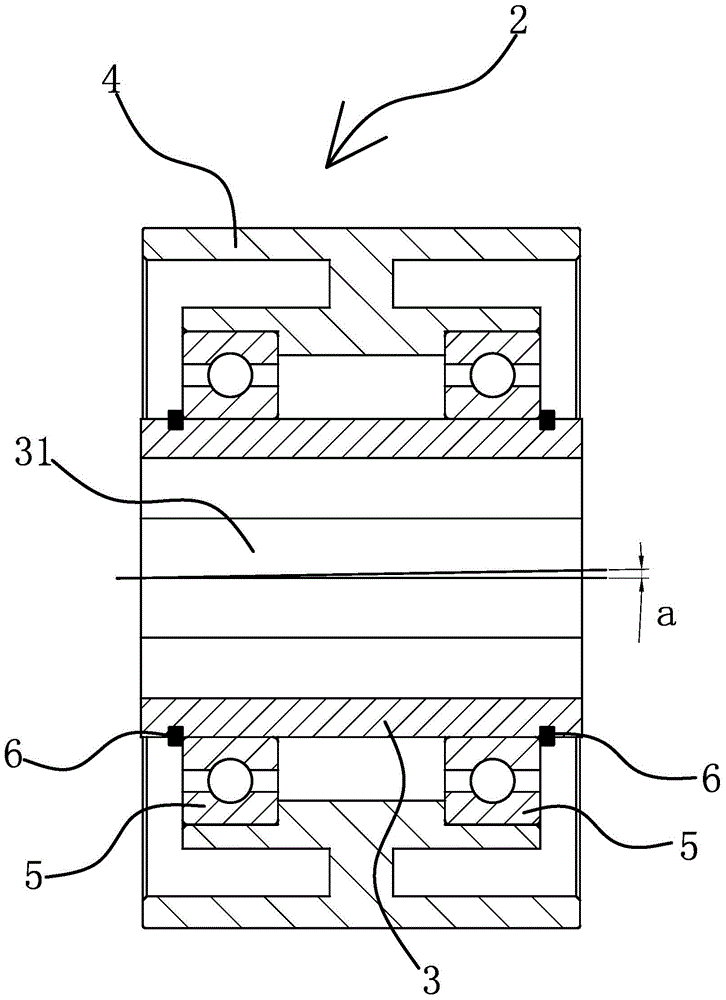
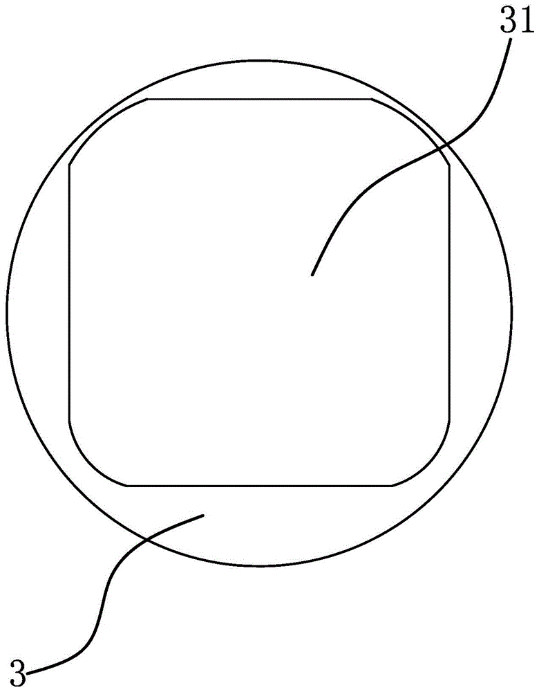
[0035] The technical solution in this embodiment is basically the same as the technical solution in Embodiment 1, the difference is that in this embodiment, the mandrel 1 has a mounting part 11 for mounting the flattening unit 2, a connecting part 12 and a mounting part 11 adopts split structure. The installation part 11 is columnar, the cross section of the installation part 11 is a centrally symmetrical polygon, and the centerline of the installation part 11 is inclined relative to the centerline of the mandrel 1 . The outer surface of the flattening unit 2 is inclined relative to the centerline of the mandrel 1 by processing the mounting portion 11 into a structure inclined relative to the centerline of the mandrel 1 . The flattening unit 2 includes an outer cover 4, and a cylindrical inner cover is arranged between each outer cover 4 and the installation part 11. The center of the inner cover has a mounting hole 31 corresponding to the shape of the installation part 11, an...

Embodiment 3

[0037] The technical solution in this embodiment is basically the same as the technical solution in Embodiment 1 or Embodiment 2, the difference is that in this embodiment, the angle a formed by the centerline of the mounting hole 31 and the centerline of the inner sleeve 3 is 0.6 degrees.


PUM


Abstract

The invention provides a flattening roller, which belongs to the technical field of machinery, and solves the problems of difficult maintenance and replacement of spare parts of an existing flattening roller. The flattening roller comprises a core shaft, wherein a plurality of cylindrical flattening units are arranged on the core shaft in a sleeved manner along the axial direction; the flattening units and the core shaft are axially located; the central line of each flattening unit inclines relative to the central line of the core shaft; each flattening unit can independently rotate relative to the core shaft; the flattening roller flattens a plastic film in a segmental flattening mode by the plurality of flattening units, so that the local axial force of the plastic film is small, transitional stretching of the plastic film is avoided, and the flattening effect of the plastic film is improved. The core shaft mounting section adopts a polygon structure, and a mounting hole in an inner sleeve of each flattening unit adopts the polygon hole matched with the mounting section, so that the circumferential position precision between the inner sleeve and the core shaft is improved; the central line of the mounting hole in the inner sleeve inclines relative to the central line of the inner sleeve, and the flattening roller is convenient to process.

Description

technical field [0001] The invention belongs to the technical field of machinery and relates to a flattening roller. Background technique [0002] During the processing or use of the plastic film, the plastic film needs to be unfolded. Due to the small thickness of the plastic film, it is easy to wrinkle, and then the processing effect is not ideal or the laying is uneven. In order to keep the plastic film in a flat state, technicians have designed and developed a flattening roller. For example, the slipping type flattening roller for vacuum coating machine disclosed in Chinese patent [application number 201220549902.7; authorized announcement number CN202898528U] includes a flattening roller The roller body, the flattening roller body is connected to the rotating shaft, the flattening roller body includes a roller and a roller core, the roller is cylindrical, and the roller core is tubular; the roller is sleeved outside the roller core to form a sliding connection; The sh...

Claims


Application Information

Patent Timeline
Patent Type & Authority Patents(China)
IPC IPC(8): B29C53/18
Inventor 林正亮
Owner 郑州华翔电子信息技术有限公司
Why Eureka
Try Eureka