Hierarchical-depressurizing oil nozzle manifold

A technology of graded pressure reduction and manifold, which is applied in wellbore/well components, earthwork drilling, sealing/packing, etc., can solve the problems of poor pressure regulation effect, unreasonable design, insufficient pressure regulation series, etc. Achieve high cost performance, improve production efficiency and prolong service life

Inactive Publication Date: 2014-04-30
CHINA NAT PETROLEUM CORP CHUANQING DRILLING ENG CO LTD CHANGQING DOWNHOLE TECH CO
View PDF5 Cites 10 Cited by
  • Summary
  • Abstract
  • Description
  • Claims
  • Application Information

AI Technical Summary

Problems solved by technology

[0003] The purpose of the present invention is to design a blowout system applicable to oil (gas) fields for the defects of insufficient pressure reduction and pressure regulation series, poor pressure reduction and pressure regulation effects, and unreasonable design of the existing blowout manifold. The multi-stage, adjustable step-down pressure relief manifold

Method used


Image

  • Hierarchical-depressurizing oil nozzle manifold

Examples


Embodiment 1

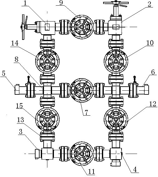
[0014] Example 1, figure 1 describe.

[0015] A graded decompression nozzle manifold, including a manifold pipeline 8, a first adjustable nozzle 1 connected to the manifold pipeline 8 through a first flat gate valve 14, and a first adjustable nozzle 1 connected to the manifold pipeline 8 through a second flat gate valve 15. The first fixed nozzle 3 connected to the manifold pipeline 8, and the first adjustable nozzle 1 and the first fixed nozzle 3 are respectively placed on both sides of the manifold pipeline 8, and are respectively placed on the manifold pipeline The second adjustable oil nozzle 2 and the second fixed oil nozzle 4 on both sides of 8, the second adjustable oil nozzle 2 and the second fixed oil nozzle 4 pass through the third flat gate valve 10, the fourth flat gate valve 12 and the tube respectively. The manifold line 8 is connected; the second adjustable oil nozzle 2 is set on the same side as the first adjustable oil nozzle 1 and placed downstream of th...

Embodiment 2

[0018] Embodiment 2, in conjunction with attached figure 1 describe.

[0019] On the basis of Embodiment 1, the valve pins of the first adjustable oil nozzle 1 and the second adjustable oil nozzle 2 are made of wedge-shaped tungsten carbide.

[0020] The first fixed oil nozzle 3 and the second fixed oil nozzle 4 adopt ceramic oil nozzles.

[0021] The flat gate valve adopts Cameron FL structure, wherein the valve plate is supersonic and adopts imported seals.

[0022] The manifold pipeline 8 is connected with API6A flanges 13 between the independent connectors.

[0023] The inner surface of the manifold pipeline 8 is made of spray-welded tungsten carbide alloy.

[0024] The fluid inlet 5 of the manifold pipeline 8 adopts a 3-1 / 16" fig1502 inlet and a 63-1 / 16" fig1502 outlet for the fluid outlet.

[0025] The optimized process and careful selection of materials in this solution make the technical effect of reducing the manifold pressure better, including but not...


PUM


Abstract

The invention relates to the field of oil/gas field blowout work depressurizing and provides a hierarchical-depressurizing oil nozzle manifold which comprises a manifold pipeline, a first adjustable oil nozzle connected with the manifold pipeline through a first flat-plate gate valve, a first fixed oil nozzle connected with the manifold pipeline through a second flat-plate gate valve, a second adjustable oil nozzle and a second fixed oil nozzle. The first adjustable oil nozzle and the first fixed oil nozzle are disposed on two sides of the manifold pipeline respectively, and the second adjustable oil nozzle and the second fixed oil nozzle are disposed on the two sides of the manifold pipeline respectively. By the hierarchical-depressurizing oil nozzle manifold, after multistage depressurizing and multiple pressure adjusting of high-pressure fluid during incoming, connection pressure reduction of a pipeline manifold and other parts is prolonged, or part replacement and maintenance probability is reduced, so that production efficiency is improved; due to preferable processing and careful material selection, technical effect of depressurizing of the manifold is better, and the advantages include but are not limited to that service lives of the above parts are prolonged, depressurizing effect is improved, and performance-cost ratio is high.

Description

technical field [0001] The invention relates to the field of depressurization in oil (gas) field spraying operations, in particular to a hierarchical depressurization spraying manifold. Background technique [0002] In oil (gas) field blowout operations, blowout manifolds play an important role. At present, most of the discharge manifolds used in the field are mainly composed of a fixed throttle valve, a flat valve, a throttle valve, and nozzles, etc., and the discharge operation is performed by replacing the nozzles. The investigation found that during the operation process, the throttling effect of a fixed throttle valve cannot meet the function of protecting downstream valves and other components, and cannot meet the needs of spraying operations. One of the most prominent problems is the low durability of the discharge pipeline and throttle nozzle, which seriously affects the construction quality and progress. Therefore, it is urgent to develop a discharge manifold that...

Claims


Application Information

Patent Timeline
Patent Type & Authority Applications(China)
IPC IPC(8): E21B33/03
Inventor 陈磊赵维斌龙庆谢平赵志华高森孙飞刘思聪李启新
Owner CHINA NAT PETROLEUM CORP CHUANQING DRILLING ENG CO LTD CHANGQING DOWNHOLE TECH CO
Why Eureka
Try Eureka