Automatic bottle removing mechanism of plastics hollow container stretching-blowing device

An empty container and stretch-blow machine technology, applied in the field of plastic machinery, can solve problems such as troublesome debugging, many wearing parts, and difficult maintenance, and achieve the effects of ensuring product quality, long service life and low maintenance rate

Inactive Publication Date: 2009-07-29
浙江东方州强塑模实业有限公司
View PDF2 Cites 10 Cited by
  • Summary
  • Abstract
  • Description
  • Claims
  • Application Information

AI Technical Summary

Problems solved by technology

The disadvantages of this type of technology are as follows: First, the patent ZL 200520100377.0 uses a single cylinder structure, which cannot achieve the effect of taking bottles. If the patent technology ZL 200620100710.2 is used, two cylinders are required, the structure is complicated, the manufacturing cost is high, and installation and debugging are difficult. Troublesome, many wearing parts, and difficult maintenance; the second is to lift the plastic bottle on one side, and the bottle mouth is easy to deform and damage the plastic bottle that has just been stretch-blown and is still in a soft state; Needs good cooperation, difficult to control, easy to cause time error

Method used


Image

  • Automatic bottle removing mechanism of plastics hollow container stretching-blowing device
  • Automatic bottle removing mechanism of plastics hollow container stretching-blowing device
  • Automatic bottle removing mechanism of plastics hollow container stretching-blowing device

Examples


Embodiment Construction

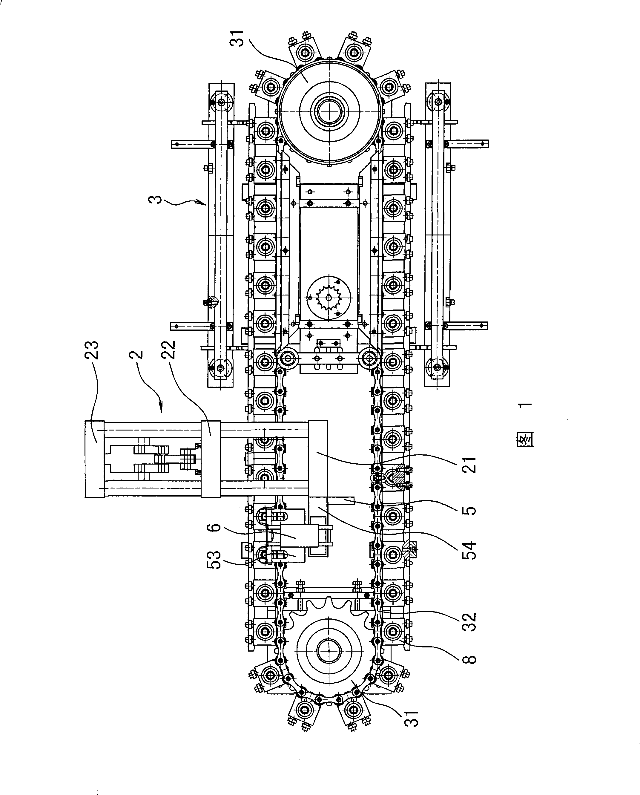
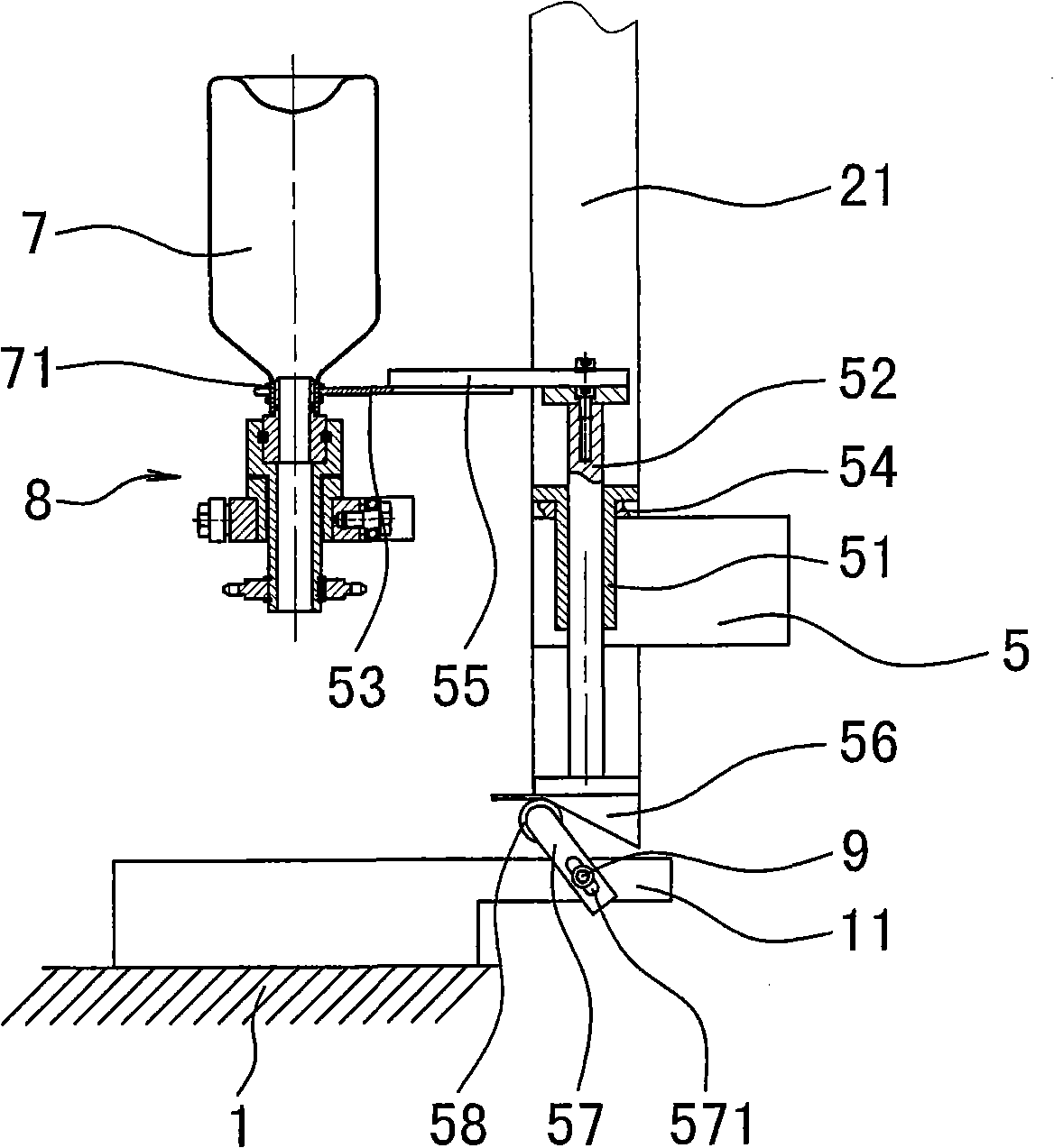
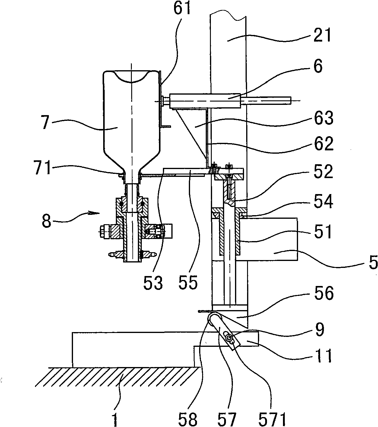
[0012] The invention discloses an automatic bottle-removing mechanism of a plastic hollow container forming stretch-blow machine, as shown in Fig. The system includes a front template 21, a middle template 22 and a rear template 23, a mold opening and closing mechanism that drives the template movement, and a stretching and blowing mechanism. The bottle tube heating system includes a sprocket 31, a chain 32 and a power delivery mechanism, and The heating device composed of the bracket and the lamp tube is characterized in that a fixed plate 5 is installed on the side of the front template 21, the fixed plate is connected with a support plate 54, a linear guide rail 51 is installed in the support plate, and there are up and down moving guide rods 52 in the linear guide rail. The bottom of 52 is in contact with the lifting top block or the cam on the frame, and the bottle-removing fork 53 is installed on the top of the guide rod, and the mouth of the bottle-removing fork 53 coope...


PUM


Abstract

The invention relates to an automatic bottle dropping mechanism of a plastic hollow container blowing and stretching machine, which comprises a machine frame. The machine frame is provided with a blowing and stretching system and a bottle pipe heating system; and the blowing and stretching system comprises a front template, a middle template, a rear template, a mould opening and closing mechanism and a blowing and stretching mechanism, wherein the mould opening and closing mechanism drives the templates to move; and the bottle pipe heating system comprises a transporting mechanism consisting of a chain wheel, a chain and power, and a heating device consisting of a bracket and a lighting tube. The mechanism is characterized in that a fixing plate is arranged on the side of the front template and connected with a supporting plate; a straight line guide rail is arranged in the supporting plate; a guide rod moving up and down is arranged in the straight line guide rail; the lower part of the guide rod contacts a lifting jacking block or a cam on the machine frame; a bottle dropping fork is arranged on the upper part of the guide rod; the opening part of the bottle dropping fork is matched with a convex ring of a plastic container; and a transverse bottle pushing device is arranged on the top of the guide rod. The bottle dropping fork arranged on the guide rod is directly driven by the self opening and closing movement of the front template to realize dropping the bottle without time difference. The mechanism does not need additional power, such as a cylinder and the like and has the advantages of simple structure and cost conservation.

Description

technical field [0001] The invention relates to an automatic bottle-removing mechanism of a plastic hollow container blow-drawing machine, which belongs to the field of plastic machinery. Background technique [0002] The plastic hollow container stretch blowing machine is mainly used for processing mineral water bottles, oil bottles and other products. According to the structure of the machine, there are many ways to take out the formed bottle during processing. One is to take the bottle by hand, including taking it directly from the mold. Bottles and bottles are taken from the operating mechanism. Manually taking bottles is labor-intensive, and secondly, the cost of labor wages is high. The other is bottle clamping or suction bottle by manipulator. Bottle clamping by manipulator is mainly used to process one or two bottles in one mold. Mechanical suction bottle can be used to process multiple bottles in one mold. The disadvantages of clamping bottle and suction bottle remo...

Claims


Application Information

Patent Timeline
Patent Type & Authority Applications(China)
IPC IPC(8): B29C49/70B29C49/56B29C49/64B29L22/00
Inventor 王自强
Owner 浙江东方州强塑模实业有限公司
Why Eureka
Try Eureka