Al technical title is built by PatSnap Al team. It summarizes the technical point description of the patent document.
A technology of wet spraying machine and jib, which is applied in the direction of shaft lining, tunnel lining, underground chamber, etc. It can solve the problems of poor control of shotcrete quality, easy rebound and collapse of concrete, and great impact on workers' health, etc. problem, achieve the effect of reducing labor intensity of workers, improving construction quality and reducing hazards
Inactive Publication Date: 2014-04-30
CHINA RAILWAY ENGINEERING EQUIPMENT GROUP CO LTD
View PDF9 Cites 8 Cited by
Summary
Abstract
Description
Claims
Application Information
AI Technical Summary
This helps you quickly interpret patents by identifying the three key elements:
Problems solved by technology
Method used
Benefits of technology
Problems solved by technology
This kind of wet spraying machine can't control the quality of sprayed concrete well, the concrete is easy to rebound and collapse, the construction quality is poor, and the efficiency is low; in addition, the spraying head is manually operated, the labor intensity of the workers is high, the dust generated by spraying is large, and the construction environment Poor, great impact on workers' health
[0004] The publication number is CN102900442A, and the name is boom system, wet spraying machine and construction machinery with the boom system. It discloses a wet spraying machine boom system scheme. The advantage of the boom system is that it has a simple structure, low The horizontal movement of the boom of the wet spraying machine is realized at a low cost. The disadvantage is that it has poor adaptability to complex surfaces, the spraying range below the ground level is small, and there are dead angles.
Method used
Image
Click on the blue label to locate the original text in one second.
Reading with bidirectional positioning of images and text.
Examples
Embodiment Construction
[0023] Below in conjunction with accompanying drawing, the present invention will be further described:
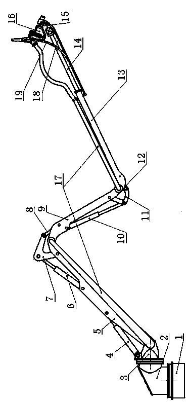
[0024] Such as figure 1 As shown, a wet spraying machine arm support system includes a base 1, a vertical turntable 2, a horizontal turntable 3, a large arm 5, a middle arm 9, a small arm 13, a telescopic arm 14, a spraying device 15, an oil cylinder, and a connecting rod , concrete delivery pipe 17, high-pressure air delivery pipe 18 and hydraulic oil pipe 19; the base 1 and the vertical turntable 2 are connected through a rotary support, and the horizontal turntable 3 is connected with the vertical turntable 2 through a rotary support; the vertical turntable 2 drives the horizontal The turntable 3 can complete the turning action, and the rotation angle range is -180°~180°; the horizontal turntable 3 is hinged to one end of the boom 5, and the first oil cylinder 4 is arranged between the horizontal turntable 3 and the boom 5 to realize the boom 5 The pitching action rel...
PUM
Abstract
The invention discloses a boom system of a wet spraying machine. The boom system of the wet spraying machine comprises a base, a vertical rotary platform, a horizontal rotary platform, a big arm, a medium arm, a small arm, a telescopic arm, a jet device, oil cylinders, a connecting rod, a concrete conveying pipe, a high-pressure air conveying pipe and a hydraulic oil pipe, wherein the base and the vertical rotary platform are connected through a rotary support, the horizontal rotary platform (3) is connected with the vertical rotary platform through a rotary support, the horizontal rotary platform is connected with one end of the big arm in a hinged mode, and the first oil cylinder is arranged between the horizontal rotary platform and the big arm. According to the boom system of the wet spraying machine, bidirectional rotation of the rotary platforms is achieved, bending of the big arm, the medium arm and the small arm, stretching and contraction of the telescopic arm, and bending between the jet device and a rotary motor are achieved, multidirectional control can be easily achieved, the working dead angle is eliminated, the jet area is greatly increased, normal spraying application operation can be carried out on sections, with different sizes, of tunnels, and complex sprayed surfaces of the tunnels, the operating range is wide, efficiency is high, labor intensity of workers is reduced, and concrete construction quality is high.
Description
technical field [0001] The invention relates to the field of engineering construction machinery, in particular to a boom system of a concrete wet spraying machine used for initial support construction of tunnel engineering, highway engineering, and side slopes. Background technique [0002] Among the existing engineering construction machinery, wet concrete spraying machine is a relatively common construction machinery. The working principle of the concrete spraying machine is to use compressed air to transport the pre-mixed concrete mixture to the nozzle of the spraying machine through the pipeline, and form a material beam after being mixed with an accelerator. On the sprayed surface, the quick-setting agent makes the concrete set and harden quickly, thus forming a concrete support layer. Shotcrete technology is widely used in various construction fields because of its simple process and economical cost. [0003] Most of the widely used spray machines are small hand-hel...
Claims
Application Information
Patent Timeline
Application Date:The date an application was filed.
Publication Date:The date a patent or application was officially published.
First Publication Date:The earliest publication date of a patent with the same application number.
Issue Date:Publication date of the patent grant document.
PCT Entry Date:The Entry date of PCT National Phase.
Estimated Expiry Date:The statutory expiry date of a patent right according to the Patent Law, and it is the longest term of protection that the patent right can achieve without the termination of the patent right due to other reasons(Term extension factor has been taken into account ).
Invalid Date:Actual expiry date is based on effective date or publication date of legal transaction data of invalid patent.
Patent Type & Authority Applications(China)
IPC IPC(8): E21D11/10
Inventor 张少华董恰王伟杨兴亚
Owner CHINA RAILWAY ENGINEERING EQUIPMENT GROUP CO LTD