A tbm special mixed injection system

A technology of mixed injection and control system, applied in wellbore lining, tunnel lining, underground chamber, etc., can solve the problems of non-customization, high cost, high TBM space requirements, reduce rebound and slump, easily control, improve The effect of equipment competitiveness

Active Publication Date: 2018-07-27
CHINA RAILWAY ENGINEERING EQUIPMENT GROUP CO LTD
View PDF6 Cites 0 Cited by
  • Summary
  • Abstract
  • Description
  • Claims
  • Application Information

AI Technical Summary

Problems solved by technology

[0004] In view of the shortcomings of the above-mentioned background technology, the present invention provides a TBM-specific mixed injection system to solve the technical problems in the prior art that the TBM has high space requirements, high cost, and cannot be customized

Method used


Image

  • A tbm special mixed injection system
  • A tbm special mixed injection system
  • A tbm special mixed injection system

Examples


Embodiment 1

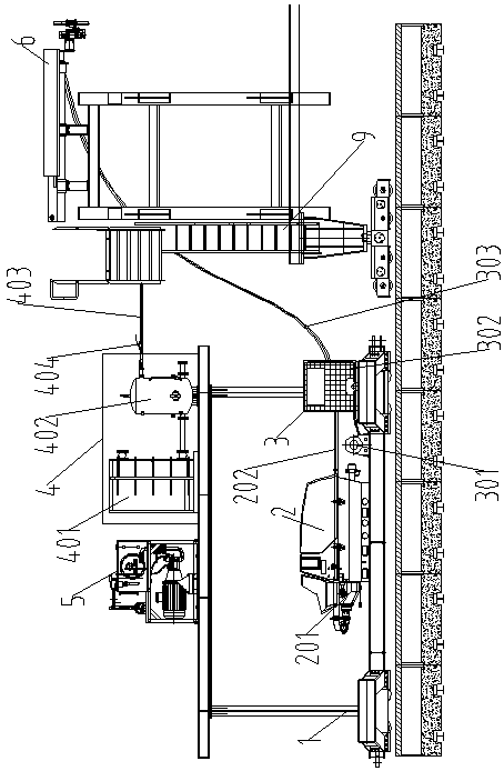
[0018] Embodiment 1: as figure 1 As shown, a special spraying system for TBM is characterized in that it includes a supporting trolley 1, a concrete pumping system 2, an additive system 3, an air compressor system 4 connected to the TBM air supply system, and a TBM hydraulic pump Station connected power source control system 5, wet spray manipulator 6 connected with walking cart 9; concrete pumping system 2, additive system 3, air compressor system 4, power source control system 5 are all installed on the rear supporting platform On the vehicle 1, the power source control system 5 is respectively connected with the concrete pumping system 2 and the wet spraying manipulator 6, and the wet spraying manipulator 6 is connected with the concrete pumping system 2, the additive system 3 and the air compressor system 4 respectively.

Embodiment 2

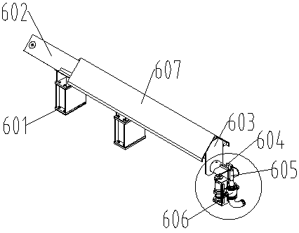
[0019] Embodiment 2: as Figure 1-3 As shown, a special spraying system for TBM includes post-supporting trolley 1, concrete pumping system 2, additive system 3, air compressor system 4 connected with TBM air supply system, and hydraulic pump station connected with TBM The power source control system 5, the wet spray manipulator 6 connected with the walking cart 9; the concrete pumping system 2, the additive system 3, the air compressor system 4, and the power source control system 5 are all installed on the supporting trolley 1, The power source control system 5 is respectively connected with the concrete pumping system 2 and the wet spraying manipulator 6, and the wet spraying manipulator 6 is connected with the concrete pumping system 2, the additive system 3 and the air compressor system 4 respectively. Described wet spray manipulator 6 comprises base 601, big arm 602, forearm 603, injection device 604, nozzle 605 and flow mixer 606, and big arm 602 is fixed on the support...

Embodiment 3

[0020] Embodiment 3: as Figure 1-4 As shown, a special spraying system for TBM includes post-supporting trolley 1, concrete pumping system 2, additive system 3, air compressor system 4 connected with TBM air supply system, and hydraulic pump station connected with TBM The power source control system 5 and the wet spraying manipulator 6 connected with the walking cart 9, the concrete pumping system 2 is placed sideways in the middle of the supporting trolley 1, and the concrete pumping system 2 includes a concrete pump 201 and a concrete delivery soft The pipe 202, the outlet end of the concrete pump 201 is connected with the input end of the conveying hose 202, which provides the driving force for conveying the concrete. Under the action of the concrete pump, the concrete enters the concrete conveying hose 202. The additive system 3 is placed sideways on the rear supporting trolley 1 and is located in front of the concrete pumping system 2. The additive system 3 includes an a...


PUM


Abstract

The invention discloses a mixed spraying system special for a TBM. The system comprises a rear matched trolley, a concrete pumping system, an additive system, an air compressor system connected with a TBM air supply system, a power source control system connected with a TBM hydraulic pump station and a wet spraying mechanical hand connected with a walking cart, the concrete pumping system, the additive system and the air compressor system are installed on the rear matched trolley, the power source control system is connected with the concrete pumping system and the wet spraying mechanical hand, and the wet spraying mechanical hand is connected with the concrete pumping system, the additive system and the air compressor system. According to the mixed spraying system, the requirement for TBM space is lowered; the power source control system and the TBM hydraulic pump station are fused, the air compressor system and the TBM air supply system are fused, the whole machine is high in TBM integration degree, and optimization of the system performance is achieved; meanwhile, the cost is greatly lowered, and the TBM equipment competitiveness is improved.

Description

technical field [0001] The invention relates to the technical field of design and construction of a full-face rock tunnel boring machine, in particular to an automatic grouting system used for TBM construction support. Background technique [0002] The full-face rock tunnel boring machine is referred to as TBM, and the open TBM and its subsequent supporting systems are generally designed and arranged with a concrete shotcrete system, so as to realize the shotcrete support operation of the tunnel while the TBM is excavating. The working principle of concrete spraying is to transport the pre-mixed concrete to the nozzle of the wet spraying machine through the pumping system, form a bundle after being mixed with accelerator, and spray it to the sprayed surface under the action of high-pressure gas to accelerate the setting. The agent makes the concrete set and harden quickly, thus forming a concrete support layer. [0003] At present, the mixed injection system of domestic TBM...

Claims


Application Information

Patent Timeline
Patent Type & Authority Patents(China)
IPC IPC(8): E21D11/10E21D9/06
CPCE21D9/0607E21D11/105
Inventor 董恰李光王伟朱英
Owner CHINA RAILWAY ENGINEERING EQUIPMENT GROUP CO LTD
Why Eureka
Try Eureka