Asphalt conveying device with preheating function

A conveying device and asphalt technology, which is applied in the direction of pipeline heating/cooling, pipes/pipe joints/fittings, mechanical equipment, etc., can solve the problems of poor asphalt conveying effect, poor fluidity, blocked channels, etc., and achieve good sealing effect, good stability effect

Active Publication Date: 2014-04-30
DONGGUAN HUAHUI PRECISION MASCH CO LTD
View PDF7 Cites 6 Cited by
  • Summary
  • Abstract
  • Description
  • Claims
  • Application Information

AI Technical Summary

Problems solved by technology

[0003] However, when transporting thermosetting materials (materials sensitive to temperature and easy to solidify), the existing rotary joints have the following deficiencies: a. Because the physical characteristics of asphalt are solidification at room temperature, the heated asphalt is transported in the pipeline. , as the temperature decreases, its viscosity gradually increases, and its fluidity becomes poor, especially for the case of long conveying pipelines, and the conveying effect of asphalt is poor; Completely cleaned, it will solidify at normal temperature and block the channel. When the hot asphalt passes through again, it will take a long time to melt it. The failure rate is high and the efficiency is low, and the mechanical seal will also be damaged; c. Some asphalt distributors and asphalt transfer stations Pipelines are heat-tracing with heat-conducting oil for canning and unloading, but heat-conducting oil heat tracing has not been fully realized for rotary joints. In actual production, the rotary joints only play the role of changing the direction of the material channel; d. Heat-conducting oil for rotary joints Heat tracing, the sealing problem between its heat transfer oil and asphalt is also an important factor limiting its development

Method used


Image

  • Asphalt conveying device with preheating function
  • Asphalt conveying device with preheating function
  • Asphalt conveying device with preheating function

Examples


Embodiment Construction

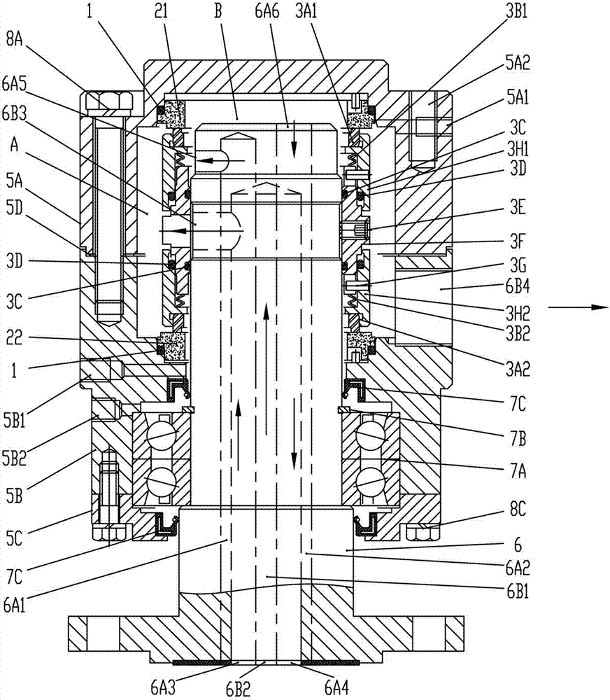
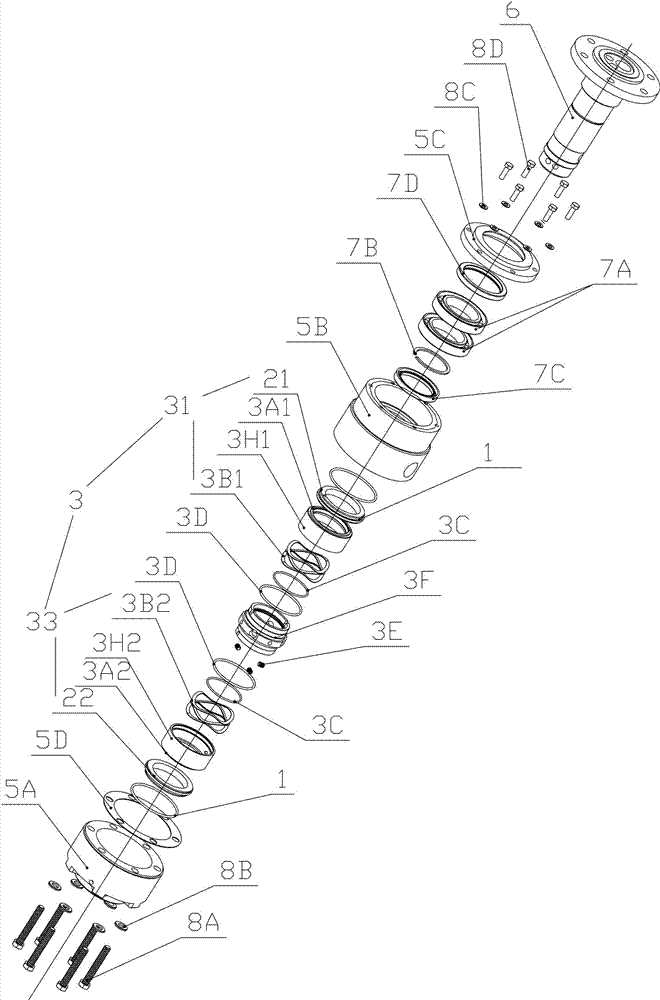
[0025] The present invention will be further described below in conjunction with accompanying drawing:

[0026] Such as Figure 1 to Figure 5 As shown, the technical solution adopted by the present invention is as follows, a kind of asphalt conveying device with preheating function is characterized in that it includes: gland (5A), bearing seat 5B, sealing assembly 3 and shaft core 6, wherein: the above shaft core 6 is provided with a first heat transfer oil channel 6A1, a second heat transfer oil channel 6A2 and an asphalt channel 6B1; the above-mentioned bearing seat 5B is sleeved on the lower part of the shaft core 6, and the above-mentioned gland 5A is sleeved on the upper part of the shaft core 6. A sealing chamber is formed between the inner wall of the cover 5A and the bearing seat 5B and the outer wall of the shaft core 6, and a dynamic ring sealing assembly 3 is arranged in the sealing chamber, and the sealing assembly 3 divides the above-mentioned sealing chamber into...


PUM


Abstract

The invention discloses an asphalt conveying device with a preheating function. The asphalt conveying device is characterized by comprising a gland, a bearing block, a sealing subassembly and a central spindle, wherein a first heat-conduction oil channel, a second heat-conduction oil channel and an asphalt channel are formed in the central spindle; the bearing block is sleeved on the lower portion of the central spindle; the gland is sleeved on the upper portion of the central spindle; a sealing cavity is formed between the gland and the outer wall of the central spindle and between the inner wall of the bearing block and the outer wall of the central spindle; a moving ring sealing subassembly is arranged in the sealing cavity; the sealing cavity is divided into shaft wall sealing space and shaft end sealing space by the sealing subassembly; and heat-conduction oil circularly flows in the heat-conduction oil channels so as to heat asphalt in the asphalt channel. By using the asphalt conveying device with the preheating function, troubles caused by the reason that temperature-sensitive media such as the asphalt remain in a rotating joint are avoided; the working efficiency of a terminal working device can be improved; the asphalt conveying device is compact in structure; a preheating part or a heat-insulation part is a built-in part; the asphalt conveying device can be assembled or disassembled integrally; and a bearing is not required to be disassembled when sealing is maintained.

Description

technical field [0001] The invention relates to an asphalt conveying device, in particular to an asphalt conveying device with a preheating function. Background technique [0002] The rotary joint, also known as the rotary joint, is a closed rotary joint that can rotate 360°. Its application fields cover almost every processing and manufacturing industry, such as: road construction, metallurgy, machine tools, thermoelectricity, petrochemical, rubber, plastics, printing and dyeing, pharmaceuticals , paper, food and other industries. In particular, the transportation of liquid media is widely used. For example, in road construction, liquid hot asphalt needs to be evenly spread according to the process. The asphalt used in construction needs to be in the temperature range of 180-200 ° C. Its viscosity is low and its fluidity is good. The traditional technology is The heated asphalt is transported to the rotary joint by the pipeline, and then sent to the nozzle through the rota...

Claims


Application Information

Patent Timeline
Patent Type & Authority Applications(China)
IPC IPC(8): F16L39/06F16L53/00
CPCF16L39/06F16L53/32
Inventor 郭文德
Owner DONGGUAN HUAHUI PRECISION MASCH CO LTD
Why Eureka
Try Eureka