Complex fillet weld joint position detecting method based on laser binocular vision

A technology of binocular vision and detection method, applied in the direction of using optical devices, measuring devices, instruments, etc., can solve the problems of poor recognition ability, low efficiency and low reliability, etc.

Active Publication Date: 2014-04-30
SOUTH CHINA UNIV OF TECH
View PDF5 Cites 38 Cited by
  • Summary
  • Abstract
  • Description
  • Claims
  • Application Information

AI Technical Summary

Problems solved by technology

[0007] In order to overcome the shortcomings of poor recognition ability, low efficiency, and low reliability existing in the existing vision-based welding seam position detection technology, the present invention makes full use of the geometric characteristics of actual fillet joints, and proposes a complex angle detection technology based on laser binocular vision. Welding seam position detection method

Method used


Image

  • Complex fillet weld joint position detecting method based on laser binocular vision
  • Complex fillet weld joint position detecting method based on laser binocular vision
  • Complex fillet weld joint position detecting method based on laser binocular vision

Examples


Embodiment Construction

[0027] The specific implementation of the present invention will be further described below in conjunction with the accompanying drawings, but the implementation and protection scope of the present invention are not limited thereto.

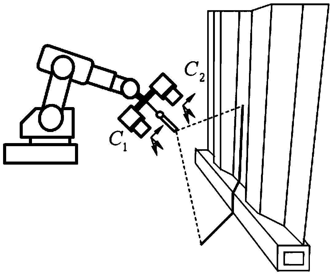
[0028] In this example, the laser scans the workpiece to form a linear laser stripe, which is collected by a CCD camera and transmitted to a computer software system for processing. The installation of the image acquisition system and the line laser on the mobile platform is as follows: figure 2 shown. Two cameras (C 1 、C 2 ) are placed sideways during installation, that is, the XOZ plane of the camera coordinate system is perpendicular to the length direction of the workpiece to be welded, and the original image of the fillet weld collected by one of the cameras is as follows image 3 It shows that the image captured by another camera has basically the same characteristics, so the processing flow is the same.

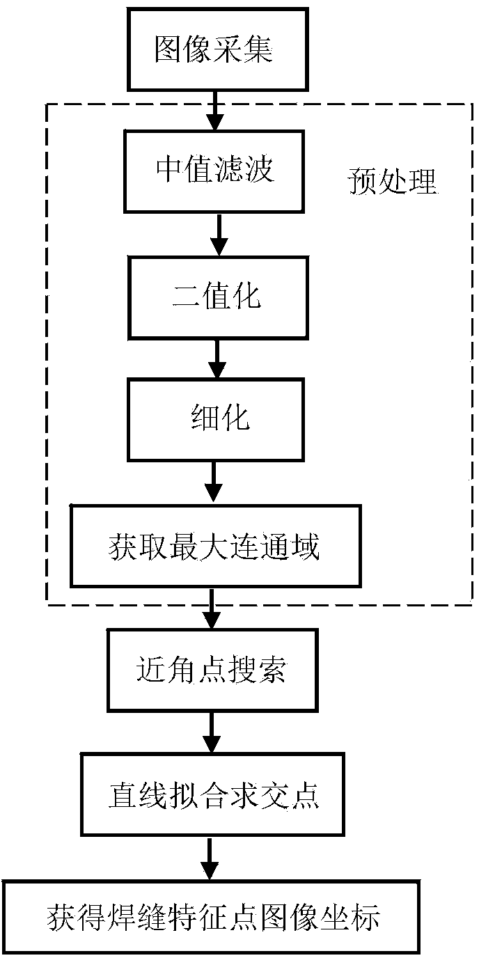
[0029] figure 1 Middle is th...


PUM


Abstract

The invention discloses a complex fillet weld joint position detecting method based on laser binocular vision. The complex fillet weld joint position detecting method based on the laser binocular vision overcomes the defect that a traditional image detecting algorithm is poor in extracting precision and extracting stability of fillet weld joint feature points. According to the technical scheme, the complex fillet weld joint position detecting method based on the laser binocular vision includes the following steps that a laser scanning workpiece is used, a binocular CCD camera is used for collecting an image, and the collected grey level image is transmitted to a software system of a computer to be processed; the processing procedures are sequentially median filtering, binarization, refining, obtaining the maximum connected domain, close angular point searching, straight line fitting and intersection point obtaining; finally, image coordinates of the weld joint feature points are obtained. The pre-processing method (median filtering, binarization, refining, obtaining the maximum connected domain) is used for removing interference of the background of the image and narrowing the retrieval range of sequential processing. A close angular point searching strategy is provided, the speed of angular point detection is improved and finally, the detection precision reaches the sub-pixel class by means of the straight line fitting and intersection point obtaining method.

Description

technical field [0001] The invention relates to the technical field of detection of complex fillet welds, in particular to a position detection method for complex fillet welds based on laser binocular vision. Background technique [0002] With the continuous development of industrial technology, the shape of welded structural parts is becoming more and more complex, such as butt or fillet welds with bends or folded lines. For these welds, in order to realize automatic welding, the automatic detection and tracking of the weld position must first be realized. At present, welding seam tracking can be realized by a variety of sensors. Among them, the sensing method of linear structured light combined with binocular vision can perform three-dimensional reconstruction of the welding head, obtain the spatial position of the welding seam, and provide path information for welding tracking. [0003] The detection of the position of the to-be-welded seam of the corner joint under the ...

Claims


Application Information

Patent Timeline
Patent Type & Authority Applications(China)
IPC IPC(8): G01B11/00
Inventor 石永华王晓佳陈熙引李学瑞
Owner SOUTH CHINA UNIV OF TECH
Why Eureka
Try Eureka