Microscopic CT motion error correction method for rotating shaft

A technology of motion error and correction method, applied in measurement devices, instruments, scientific instruments, etc., can solve the problems of reducing three-dimensional spatial resolution and error of CT reconstruction results, etc.

Active Publication Date: 2014-04-30
TIANJIN UNIV
View PDF5 Cites 8 Cited by
  • Summary
  • Abstract
  • Description
  • Claims
  • Application Information

AI Technical Summary

Problems solved by technology

Therefore, the movement error of the rotation axis of the rotating sample stage of a few microns will undoubtedly lead to errors in the CT reconstruction results, thereby reducing its three-dimensional spatial resolution

Method used


Image

  • Microscopic CT motion error correction method for rotating shaft
  • Microscopic CT motion error correction method for rotating shaft
  • Microscopic CT motion error correction method for rotating shaft

Examples


Embodiment Construction

[0032] The purpose of the present invention is to provide a method for correcting the movement error of the micro-CT rotating shaft so as to improve the three-dimensional spatial resolution of the micro-CT reconstruction results. The measurement method is simple, practical and reliable.

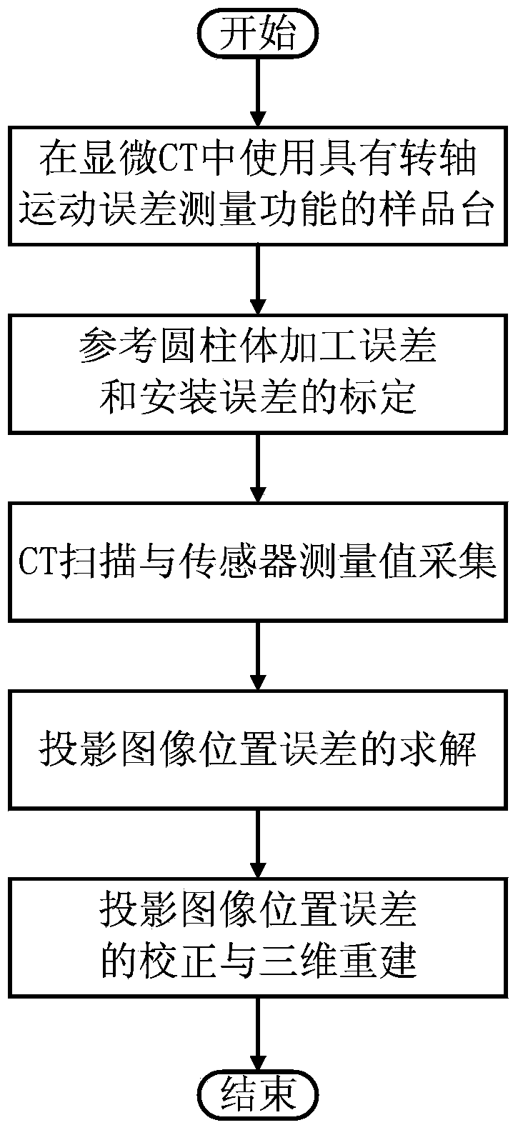
[0033] The present invention is achieved through the following technical solutions, a method for correcting the movement error of a micro-CT rotating shaft, which is characterized in that it includes the following steps:

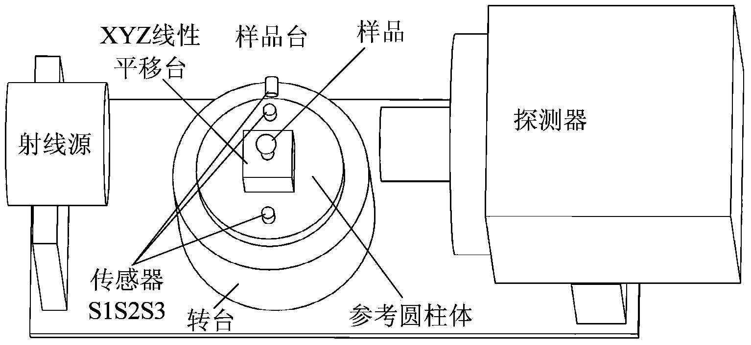
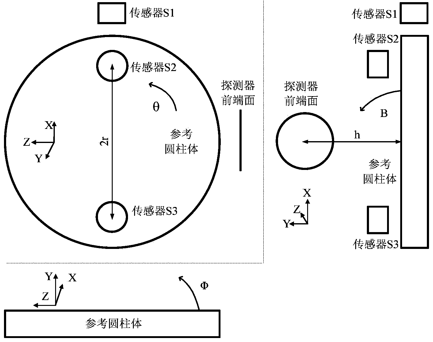
[0034] (1) Install a capacitive sensor and a reference cylinder on the rotating sample stage in micro-CT to monitor the error movement of the rotating shaft;

[0035] (2) Calibrate the machining error and installation error of the reference cylinder in the sample stage with the function of measuring the rotation axis error motion;

[0036] (3) During the CT scanning process, the measurement values ​​of the three sensors S1S2S3 are collected while collecting each projection im...


PUM


Abstract

The invention relates to the field of application of numerical control machining and measurement equipment in order to improve the three-dimensional space resolution of a microscopic CT reestablishment result, and a measurement method is simple, practical and reliable. Thus, according to the adopted technical scheme, a microscopic CT motion error correction method for a rotating shaft includes the following steps that first, displacement sensors and a reference cylinder are additionally arranged on a rotating sample platform in a microscopic CT so as to monitor the error motion of the rotating shaft; second, the machining error and the mounting error of the reference cylinder in the sample platform with the rotating shaft error motion measurement function can be calibrated; third, in the CT scanning process, measured values of three sensors are simultaneously collected when all projected images are collected; fourth, the position errors of all the projected images caused by the motion error of the rotating shaft are solved; fifth, the position errors of all the projected images are corrected and the projected images are reestablished three-dimensionally. The microscopic CT motion error correction method for the rotating shaft is mainly applied to the numerical control machining and measurement equipment.

Description

technical field [0001] The present invention relates to the application field of numerical control machining and measuring equipment. Specifically, the present invention relates to a method for correcting the movement error of a rotating shaft, in particular to a method for correcting the moving error of a rotating shaft in the process of micro-CT scanning. Background technique [0002] Traditional CT (Computed Tomography, computerized tomography) technology (including medical CT and industrial CT) can perform three-dimensional reconstruction of the internal structure of the measured object, and has already become an important technical means in the field of non-destructive testing, and its resolution is generally at the millimeter level. Micro-CT can achieve higher spatial resolution, and its emergence makes it possible to perform high-resolution three-dimensional imaging of the interior of the sample. Compared with traditional CT, micro-CT uses micro-focus ray sources (or ...

Claims


Application Information

Patent Timeline
Patent Type & Authority Applications(China)
IPC IPC(8): G01B15/04G01N23/00
Inventor 胡晓东邹晶须颖赵耕砚陈津平胡小唐
Owner TIANJIN UNIV
Why Eureka
Try Eureka