On-site test method for radar speed detector

A radar speedometer and on-site detection technology, applied in the detection field, can solve problems such as low accuracy, lack of safety, and vehicle speed, and achieve the effects of reducing work intensity and pressure, realizing data reproduction, and strong safety

Inactive Publication Date: 2014-04-30
林仲扬
View PDF2 Cites 17 Cited by
  • Summary
  • Abstract
  • Description
  • Claims
  • Application Information

AI Technical Summary

Problems solved by technology

[0023] ① Lack of safety: The verification method of judging the installation angle of the radar speedometer by running on the actual road requires the vehicle to run at a high speed, which is undoubtedly very dangerous in actual traffic conditions
[0024] ②The accuracy is not high: due to the different slope conditions on the road, the wind direction and wind speed are changing at any time, so the car cannot drive at an accurate and constant speed, which makes the accuracy of the standard speed of the car not high, resulting in low detection accuracy
[0025] ③The data cannot be reproduced. Due to the characteristics of the motor vehicle and the changes in various external conditions, our vehicle cannot repeatedly run at the same speed twice, and the measurement data cannot be reproduced.
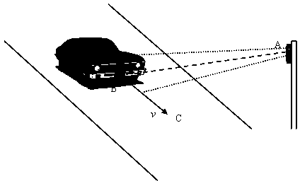
[0026] ④ It is impossible to determine the actual installation angle of the radar speedometer. Since the motor vehicle radar speedometer is generally installed on the side of the road or above the road, we often cannot accurately measure the radar speedometer and the driving direction of the motor vehicle when testing the radar speedometer. The included angle and the area radiated by the radar speedometer, let alone simulate the signal reflected by the motor vehicle through the radiated area to the radar speedometer
The workload is very heavy, sometimes it takes several days for a radar speedometer to detect

Method used


Image

  • On-site test method for radar speed detector
  • On-site test method for radar speed detector
  • On-site test method for radar speed detector

Examples


Embodiment 1

[0059] This embodiment detects the radar speedometer. On a certain road where the radar speedometer is installed, according to the method of the present invention, the angle α, α 1 、α 2 And the distance L between the two positions at the 3dB point of the radiation field strength of the radar speedometer is (19.0°, 22.0°, 25.0° and 4.7m), respectively. (The detected lane is 2 lanes)

[0060] Using a microwave frequency meter, it is detected that the emission frequency of the radar speedometer is 35.098GHz, and the error is -2MHz (this indicator should meet ≦100MHz as stipulated in the national verification regulations).

[0061] Input the speed just detected (19.0°, 22.0°, 25.0° and 4.7m) and the speed to be verified on the moving target speed simulation device, such as 120km / h, and the moving target speed simulation device will send the simulated motor vehicle to the radar speedometer The Doppler signal when passing at 120km / h shows 119km / h on the radar speedometer. The spe...

Embodiment 2

[0063] This embodiment detects the radar speedometer. On a certain road where the radar speedometer is installed, according to the method of the present invention, the angle α, α 1 、α 2 And the distance L between the two positions at the 3dB point of the radiation field strength of the radar speedometer is (27.0°, 30.0°, 33.0° and 2.6m), respectively. (The detected lane is 2 lanes)

[0064] Using a microwave frequency meter, it is detected that the emission frequency of the radar speedometer is 24.165GHz, and the error is 15MHz (this indicator should meet ≦45MHz as stipulated in the national verification regulation JJG528).

[0065] Input the speed just detected (27.0°, 30.0°, 33.0° and 2.6m) and the speed to be verified on the moving target speed simulation device, such as 150km / h, and the moving target speed simulation device will send the simulated motor vehicle to the radar speedometer The Doppler signal when passing at 150km / h shows 146km / h on the radar speedometer. Th...

Embodiment 3

[0067] This embodiment detects the radar speedometer. On a certain road where the radar speedometer is installed, according to the method of the present invention, the angle α, α 1 、α 2 And the distance L between the two positions at the 3dB point of the radiation field strength of the radar speedometer is (27.0°, 30.0°, 33.0° and 1.2m), respectively. (The detected lane is 1 lane)

[0068] Using a microwave frequency meter, it is detected that the emission frequency of the radar speedometer is 24.165GHz, and the error is 15MHz (this indicator should meet ≦45MHz as stipulated in the national verification regulation JJG528).

[0069] Input the speed just detected (27.0°, 30.0°, 33.0° and 1.2m) and the speed to be verified on the moving target speed simulation device, such as 150km / h, and the moving target speed simulation device will send the simulated motor vehicle to the radar speedometer The Doppler signal when passing at 150km / h shows 146km / h on the radar speedometer. The...


PUM


Abstract

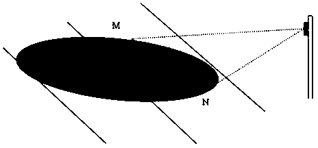
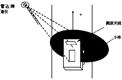
The invention discloses an on-site test method for a radar speed detector. The method includes the steps of enabling a small vehicle provided with a microwave antenna matched with the radar speed detector to pass through the radiation area of the radar speed detector in the running direction of the vehicle on a road provided with the radar speed detector, finding the point with the maximum power and the points with the power 3 dB lower than the maximum power, measuring a physical included angle alpha between the radar speed detector and the running vehicle, an angle alpha 1, generated when the vehicle enters one of the points with the power 3 dB lower than the maximum power, between the radar speed detector and the running vehicle, an angle alpha 2, generated when the vehicle leaves the other point with the power 3 dB lower than the maximum power, between the radar speed detector and the running vehicle, and the distance L between the position where the vehicle enters the one of the points with the power 3 dB lower than the maximum power and the position where the vehicle leaves the point with the power 3 dB lower than the maximum power, measuring the microwave transmitting frequency of the radar speed detector to obtain the error of the microwave transmitting frequency of the radar speed detector, imputing alpha 1, alpha 2, L and a speed to be detected into a moving target speed simulation device, and detecting the speed error of the radar speed detector through the moving target speed simulation device. The on-site test method is high in safety performance, high in accuracy and high in stability, and enables data to reappear, work pressure of technical staff is reduced, and work intensity of the technical staff is lowered.

Description

technical field [0001] The invention relates to a detection method, in particular to a field detection method of a radar speedometer. Background technique [0002] The use of radar speedometers to detect the speed of motor vehicles is a very mature and most commonly used detection method in the world at present. It can simply, quickly, flexibly and accurately measure the speed of motor vehicles that need to be determined. [0003] The basic principle of using a radar speedometer to detect the speed of a motor vehicle is: the Doppler principle. The radar speedometer mainly applies the Doppler principle. When a radar beam with a certain transmission frequency hits a moving target, its reflection frequency carries the target speed information. The reflection frequency is different from the transmission frequency. The difference between the two is called Doppler. Frequency, the Doppler frequency is proportional to the moving speed of the target. When the target is close to the...

Claims


Application Information

Patent Timeline
Patent Type & Authority Applications(China)
IPC IPC(8): G01S7/40
CPCG01S7/40
Inventor 林仲扬
Owner 林仲扬
Why Eureka
Try Eureka