A multi-beam splitter
A beam splitter and multi-beam technology, applied in the field of lasers, can solve the problems of complex multi-beam beam splitting structure and limited beam splitting ability, and achieve the effects of lowering the production cost, improving the yield rate and simplifying the structure.
- Summary
- Abstract
- Description
- Claims
- Application Information
AI Technical Summary
Problems solved by technology
Method used
Image
Examples
Embodiment 1
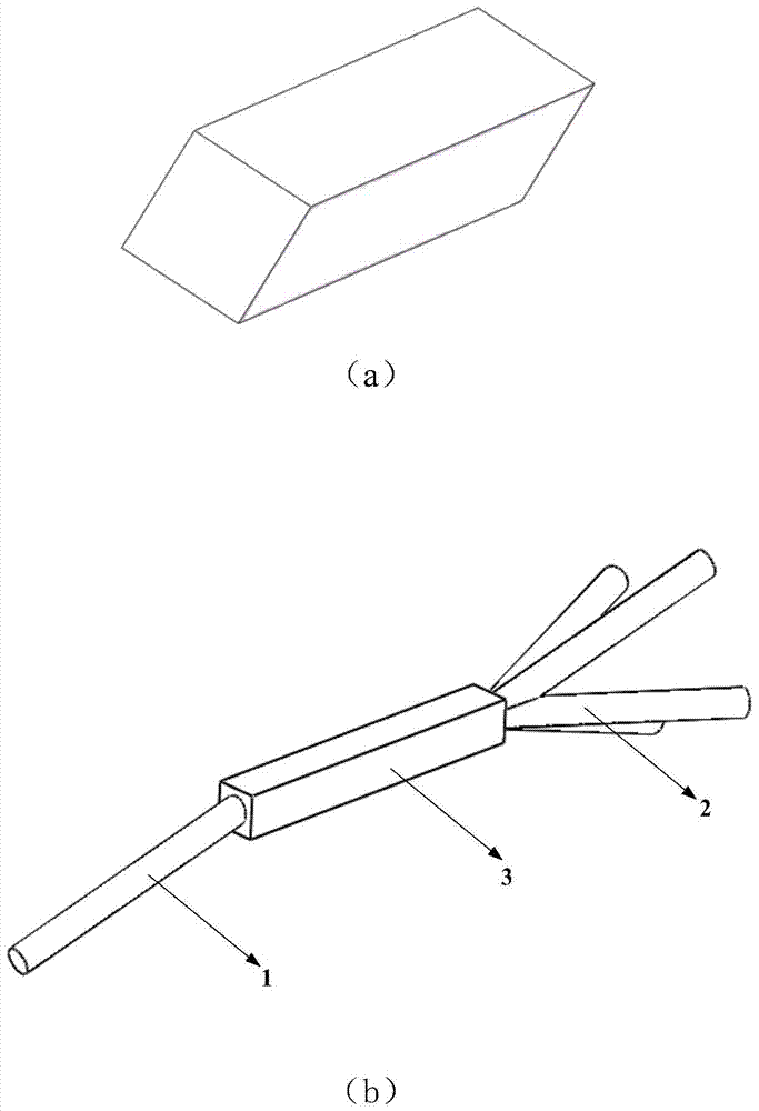
[0066] The multi-beam splitter provided by the present invention, such as figure 1 (a). The cross section of the optical waveguide is a square, that is, an equilateral polygon with the number of sides L=4. The optical waveguide is a solid optical waveguide, and both ends of the optical waveguide are coated with high antireflection films. During operation, the beam to be split is at an acute angle with the main axis of the optical waveguide, and is incident from one end of the optical waveguide. The incident angle of the incident light beam on the side surface is greater than the total reflection angle, so that total reflection is formed on the side surface of the optical waveguide.
[0067] The beam is reflected multiple times in the multi-beam splitter, passes through the beam splitter in a spiral shape, exits from the other end of the beam splitter, and is evenly divided into multiple parts, such as figure 1 (b) shown.
[0068] The number of sides of the cross section of...
Embodiment 2
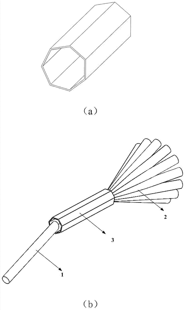
[0073] The multi-beam splitter provided by the present invention, such as figure 2 (a). The cross section of the optical waveguide is a regular heptagon, that is, L=7, the optical waveguide is a hollow optical waveguide, and the inner wall of the optical waveguide is coated with a total reflection film.
[0074] When working, the beam to be split is at an acute angle with the main axis of the optical waveguide, and is incident from one end of the optical waveguide. The light beam after starting is reflected multiple times on different sides of the optical waveguide in the interior of the optical waveguide. Since the inner wall of the optical waveguide is coated with a total reflection film, it can be approximated that the light beam is completely reflected.
[0075] The beam is reflected multiple times in the multi-beam splitter, passes through the beam splitter in a spiral shape, exits from the other end of the beam splitter, and is evenly divided into multiple beams, such ...
Embodiment 3
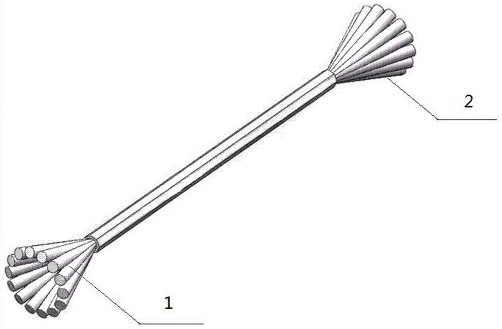
[0081] Applying the multi-beam splitter beam splitting method provided by the present invention, the multi-beam beam splitter is such as figure 1 As shown in (a), it is a cylindrical optical waveguide, and the cross-section of the optical waveguide is a square, that is, an equilateral polygon with the number of sides L=4. The optical waveguide is a solid optical waveguide, and both ends of the optical waveguide are coated with high antireflection films.
[0082] During operation, the beam to be split is at an acute angle with the main axis of the optical waveguide, and is incident from one end of the optical waveguide. The incident angle of the incident light beam on the side surface is greater than the total reflection angle, so that total reflection is formed on the side surface of the optical waveguide.
[0083] The light beam is reflected multiple times in the multi-beam splitter, passes through the beam splitter in a spiral shape, exits from the other end of the beam spl...
PUM
 Abstract
Description
Claims
Application Information
 - R&D
- Intellectual Property
- Life Sciences
- Materials
- Tech Scout
- Unparalleled Data Quality
- Higher Quality Content
- 60% Fewer Hallucinations
Browse by: Latest US Patents, China's latest patents, Technical Efficacy Thesaurus, Application Domain, Technology Topic, Popular Technical Reports.
© 2025 PatSnap. All rights reserved.Legal|Privacy policy|Modern Slavery Act Transparency Statement|Sitemap|About US| Contact US: help@patsnap.com


