

Intelligent public transport information interaction and display system
An information interaction and display system technology, applied in traffic control systems, road vehicle traffic control systems, instruments, etc., can solve the problems of poor compatibility, high complexity, and few functions of the bus electronic stop sign system, and achieve friendly man-machine The interface, the reduction of the amount of transmitted data, and the effect of complete structure and function
- Summary
- Abstract
- Description
- Claims
- Application Information
AI Technical Summary
Problems solved by technology
Method used
Image

Examples
Embodiment Construction
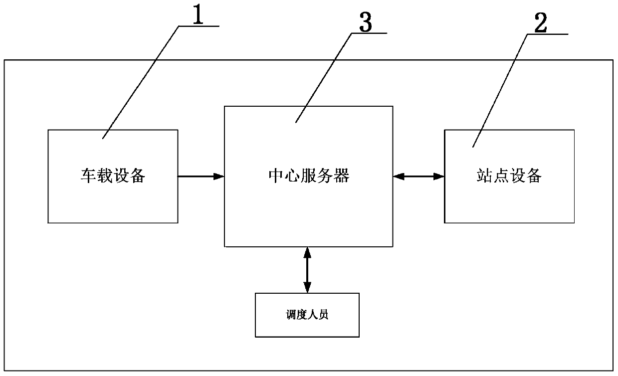
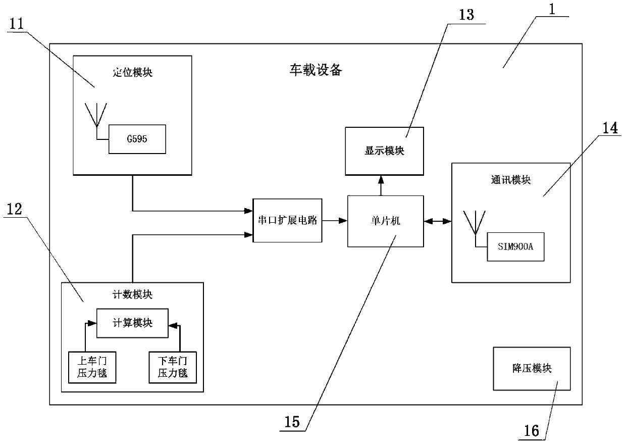
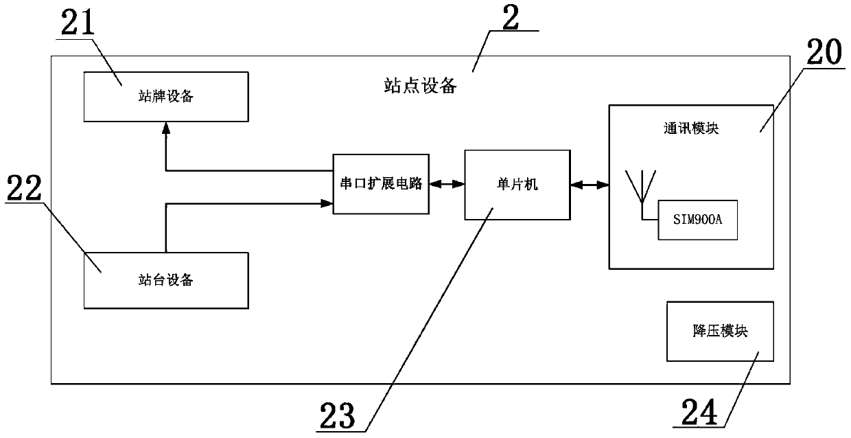
[0033] see figure 1 , figure 2 , image 3 , Figure 4 with Figure 5 Shown:
[0034] The intelligent public transportation information interaction and display system of the present invention includes a vehicle-mounted device 1, a station device 2 and a central server 3, wherein the vehicle-mounted device 1 can realize vehicle positioning and congestion degree judgment and compare vehicle position information and congestion degree information Send to the central server 3, and receive the scheduling information sent by the central server 3 at the same time, the central server 3 can realize the screening, allocation and transmission of vehicle location information and congestion degree and realize the scheduling of buses, and the station equipment 2 receives the dispatching information sent by the central server 3 Vehicle information (including location information and congestion degree information), and realize the display of location and congestion degree, and at ...
PUM
 Abstract
Description
Claims
Application Information