Data transmission device and method

A technology of a data transmission device and a data transmission method, applied in the field of data transmission, can solve the problems of crosstalk, error code packet loss, poor scalability, etc., and achieve the effect of increasing the rate, saving the backplane bus, and ensuring the transmission accuracy

Active Publication Date: 2014-04-30
北京格林伟迪科技股份有限公司 +1
View PDF4 Cites 7 Cited by
  • Summary
  • Abstract
  • Description
  • Claims
  • Application Information

AI Technical Summary

Problems solved by technology

The common bus connection method reduces the density of backplane wiring, but has strict requirements on the clock and phase relationship of each board. When the rate is high, problems such as bit error and packet loss are prone to occur.
In the independent bus connection mode, more backplane wiring and terminals are used. With the increase of branch boards and the increase in information transmission requirements, the design difficulty of the backplane and the system is increased. If a backplane is required The increase in the number of PCB layers requires an increase in the number of terminals. At the same time, the later expansion is also poor. Improper handling can easily cause problems such as signal reflection and crosstalk.

Method used


Image

  • Data transmission device and method
  • Data transmission device and method
  • Data transmission device and method

Examples


Embodiment Construction

[0043] In order to make the object, technical solution and advantages of the present invention clearer, the present invention will be described in detail below through specific embodiments and with reference to the accompanying drawings.

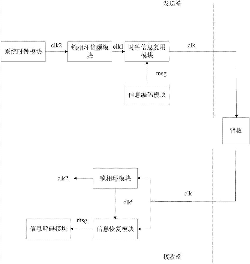
[0044] The invention provides a data transmission device, such as figure 2As shown, it includes: a backplane, and several boards interconnected through the backplane. It is characterized in that the data transmission device includes the following modules carried on each board: when the board is used as the sending end of information synchronization, it is Triggered system clock module, phase-locked loop frequency multiplier module, information encoding module and clock information multiplexing module; and, when the board is used as the receiving end of information synchronization, the triggered phase-locked loop module, information recovery module and information decoding module .

[0045] On the sender side:

[0046] The system clock mod...


PUM


Abstract

The invention discloses a data transmission device. The data transmission device comprises a sending end, a system clock module, a phase-locked loop frequency doubling module, an information coding module, a clock information multiplexing module, a receiving end, a phase-locked loop module, an information recovery module and an information decoding module, wherein the system clock module is used for generating system clock signals, the phase-locked loop frequency doubling module is used for generating frequency doubling clock signals according to the system clock signals, the information coding module is used for generating discrete digital coding signals to be jointly transmitted to the clock information multiplexing module, the clock information multiplexing module is used for generating coding clock signals to be transmitted to a backplane according to the digital coding signals, the phase-locked loop module is used for generating recovery clock signals according to the received coding clock signals, the information recovery module is used for sampling the coding clock signals according to the recovery clock signals and restoring the coding clock signals to obtain the digital coding signals, and the information decoding module is used for decoding the digital coding signals to obtain digital information. In this way, transmission of the clock signals and the information signals can be achieved only through one bus, and backplane buses are saved. The invention further provides a data transmission method.

Description

technical field [0001] The present invention relates to the technical field of data transmission, in particular to a data transmission device and method. Background technique [0002] Many communication devices, such as SDH equipment and PTN equipment, adopt a multi-slot chassis system structure, and the boards and cards in each slot are interconnected by the backplane. The communication equipment system requires the system clock to be synchronized, so the recovery and distribution of the synchronous clock and the transfer of related information are an important issue for the design of the communication equipment system. In addition to the system clock, there are many other important information in the communication equipment system that need to be transmitted through the backplane, such as overhead in SDH, time information in PTN, and frame header of the system. A device is often composed of more than a dozen boards, and the transmission of these information places higher ...

Claims


Application Information

Patent Timeline
Patent Type & Authority Applications(China)
IPC IPC(8): H04L7/033H04L1/00
Inventor 陈江峰张新辉
Owner 北京格林伟迪科技股份有限公司
Why Eureka
Try Eureka