
Spray gun for wet-type sand blasting

A sandblasting and spray gun technology, applied in the direction of spray guns, explosion generating devices, abrasives, etc., can solve problems such as enlargement, large demand, and inability to use slurry effectively.

Inactive Publication Date: 2014-05-07
TOSHIBA MASCH CO LTD
View PDF8 Cites 4 Cited by
  • Summary
  • Abstract
  • Description
  • Claims
  • Application Information

AI Technical Summary

Problems solved by technology

Therefore, the amount of overflow of both ends in the width direction of each slurry projection area toward the outside of the width Y of the workpiece W increases, and accordingly there is a problem that not only the injected slurry cannot be used effectively, The slurry receiving part B on the opposite side of the workpiece needs to be considerably larger than when only one spray gun is used
Therefore, due to the difference in the form of each slurry pipe and each air pipe, there may be a deviation between the slurry projected from one spray gun and the slurry projected from the other spray gun, and the desired wet blasting effect cannot be obtained.

Method used


Image

  • Spray gun for wet-type sand blasting
  • Spray gun for wet-type sand blasting
  • Spray gun for wet-type sand blasting

Examples


Embodiment Construction

[0028] Below, refer to Figure 1 to Figure 8 , the first embodiment of the present invention will be described.

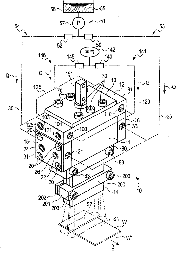
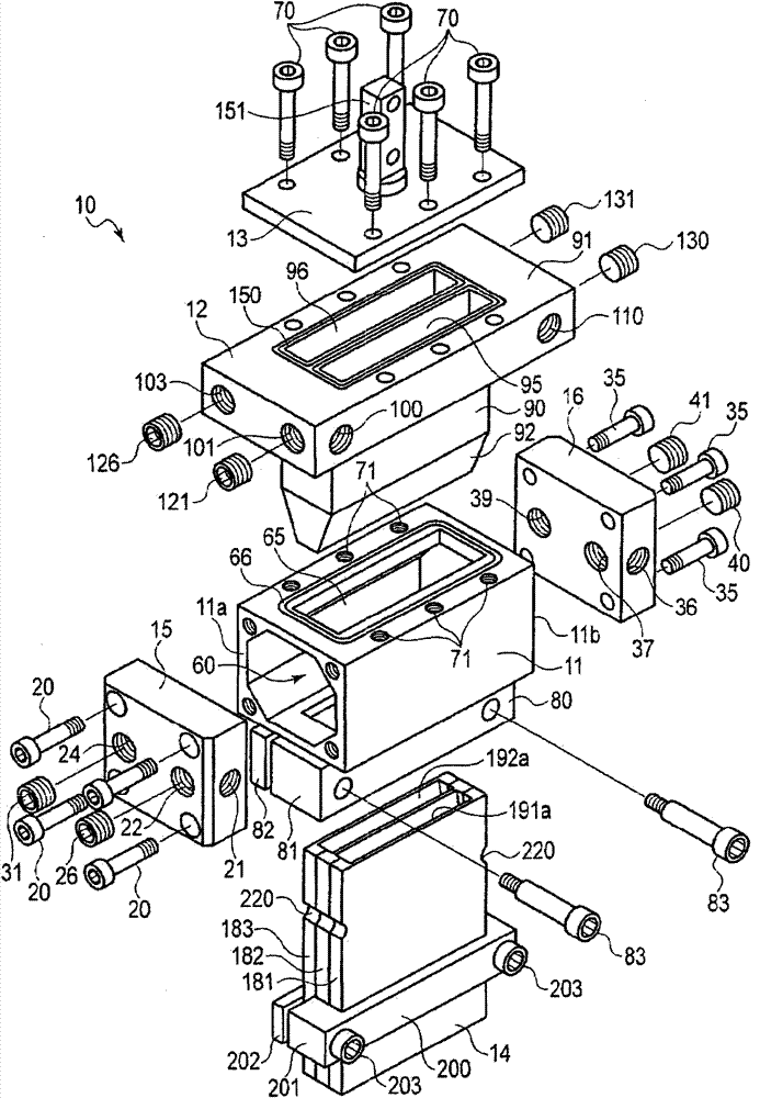
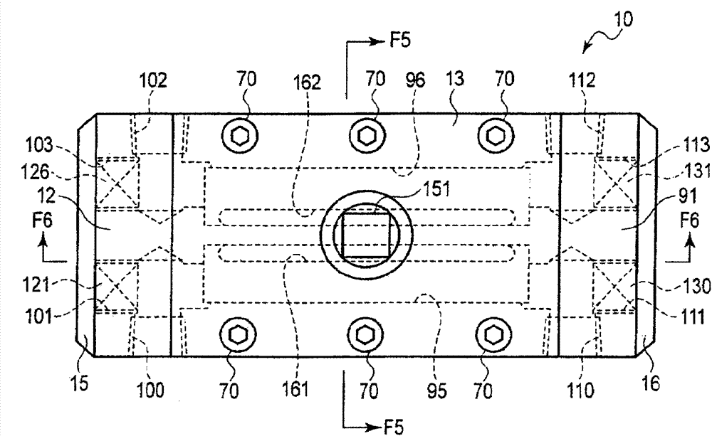
[0029] figure 1 It is a perspective view of the wet blasting torch 10 (hereinafter simply referred to as torch 10 ) of the first embodiment. figure 2 is an exploded perspective view of the spray gun 10, image 3 is a plan view of the spray gun 10 . Figure 4 It is a top view schematically showing the workpiece W and the torch 10 installed above the workpiece W. FIG. The workpiece W is continuously moved in a direction indicated by an arrow F by a conveyance mechanism 1 including, for example, a timing belt or the like.

[0030] figure 1 Shown spray gun 10 comprises: hollow gun main body 11, is located at gun main body 11 sides ( figure 2 The air injection member 12 and the cover member 13 are located on the other side of the gun main body 11 (upper side in figure 2 The nozzle member 14 on the lower side of the gun body 11, and a pair of connecting blocks...


PUM


Abstract

Provided is a spray gun for wet-type sand blasting. A first slurry chamber (61) and a second slurry chamber (62) are disposed in a gun main body (11). An air injection component (12) is provided with a first air chamber (95), a second air chamber (96), a first ventilation portion (161), a second ventilation portion (162), a first air bursting portion (171), and a second air bursting portion (172). A nozzle component (14) is provided with a first spraying circulating portion (191) and a second spraying circulating portion (192) whose flow paths sections are in slot shape, and slurry projection ports (230,231). An inlet side opening (191a) of the first spraying circulating portion (191) has an opening towards the first slurry chamber (61). The first air bursting portion (171) of the air injection component (12) is opposite to the inlet side opening (191a) of the nozzle component (14). An inlet side opening (192a) of the second spraying circulating portion (192) has an opening towards the second slurry chamber (62). The second air bursting portion (172) is opposite to the inlet side opening (192a).

Description

technical field [0001] The present invention relates to a spray gun for wet sand blasting which sprays slurry containing an abrasive in liquid toward a workpiece. Background technique [0002] As a kind of blasting device used in the surface treatment of workpieces, etc., there are known, for example, Japanese Patent Laid-Open No. 2008-229798 (Patent Document 1) or Japanese Patent Laid-Open No. 2011-115889 (Patent Document 1). 2) As described above, the wet blasting apparatus performs surface treatment of a workpiece by spraying the slurry containing the abrasive in the liquid toward the workpiece. The wet blasting apparatus includes: a spray gun having a nozzle that sprays slurry together with air toward a workpiece; and a slurry supply system and an air supply system that supply slurry and compressed air It is pressure-fed to the spray gun, whereby the slurry is projected toward the workpiece from the nozzle. Wet sandblasting is also sometimes called liquid honing (Japan...

Claims


Application Information

Patent Timeline
Patent Type & Authority Applications(China)
IPC IPC(8): B24C5/02B24C5/04B24C7/00
CPCB24C5/04B24C7/0007
Inventor 牧野真一
Owner TOSHIBA MASCH CO LTD
Learn More