A wire rope stress relief device

A stress-relieving and wire rope technology, applied in the field of auxiliary production of wire ropes, can solve the problem that the effect cannot fully meet the production of high-quality wire ropes, etc., and achieve the effect of eliminating the stress of wire rope strands

Active Publication Date: 2016-04-27
JIANGSU SAFETY STEEL WIRE ROPE
View PDF8 Cites 0 Cited by
  • Summary
  • Abstract
  • Description
  • Claims
  • Application Information

AI Technical Summary

Problems solved by technology

[0002] At present, with the refined development of steel wire rope processing, the production of high-quality steel wire ropes has become the goal of various manufacturers. However, the conventional method for stress relief of steel wire rope strands is realized through pulley blocks arranged horizontally and vertically, and its effect cannot fully meet the technical requirements for producing high-quality steel wire ropes. Require

Method used


Image

  • A wire rope stress relief device

Examples


Embodiment Construction

[0014] The technical solutions of the present invention will be further described below in conjunction with the accompanying drawings and through specific implementation methods.

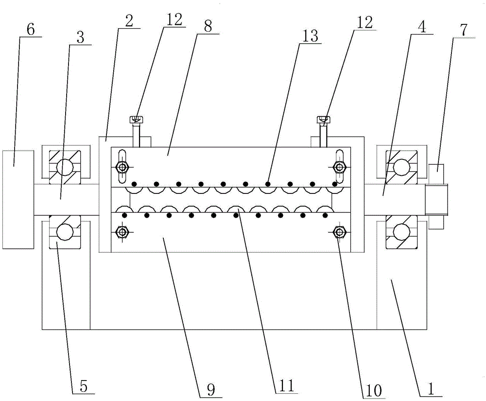
[0015] see figure 1 as shown, figure 1 It is a structural schematic diagram of the steel wire rope stress relief device provided in Embodiment 1 of the present invention.

[0016] In this embodiment, a wire rope stress relief device includes a support 1 and a fixed seat 2, the two ends of the fixed seat 2 are respectively connected with an optical axis 3 and a main shaft 4, and both sides of the support 1 are equipped with bearings 5. The optical shaft 3 and the main shaft 4 are correspondingly assembled in the bearing 5, and the outer end of the optical shaft 4 is connected to a transmission pulley 6, and the transmission pulley 6 is driven by a drive motor through a transmission belt. The outer end of the main shaft 4 passes through the bearing 5 and is installed with a fixed ring 7 through the ...


PUM


Abstract

The invention discloses a steel wire rope destressing device which comprises a supporting base and a permanent seat, wherein two ends of the permanent seats are respectively connected with an optical shaft and a main shaft; two sides of the supporting base are provided with bearings; the optical shaft and the main shaft are correspondingly assembled in the bearings; the outer end of the optical shaft is connected with a driving component; the outer end of the main shaft penetrates through the bearing and is provided with a retaining ring by virtue of end threads; the permanent seat is sequentially provided with a push plate and a dead plate from top to bottom; multiple pulleys are correspondingly arranged on the push plate and the dead plate; the top of the permanent seat is provided with an adjusting screw for regulating the height of the push plate; the end part of the adjusting screw props against the push plate. According to the destressing device, the whole device is driven by virtue of the driving component to rotate 360 degrees; meanwhile, the adjusting screw is used for regulating the amount of draught of the pulley relative to a steel wire rope strand, so that the effect of destressing the strand in a 360-degree manner can be realized; not only can the stress of the steel wire rope strand be eliminated, but also a solid foundation is laid for producing qualified steel wire ropes.

Description

technical field [0001] The invention relates to a steel wire rope auxiliary production technology, in particular to a steel wire rope stress relief device. Background technique [0002] At present, with the refined development of steel wire rope processing, the production of high-quality steel wire ropes has become the goal of various manufacturers. However, the conventional method for stress relief of steel wire rope strands is realized through pulley blocks arranged horizontally and vertically, and its effect cannot fully meet the technical requirements for producing high-quality steel wire ropes. Require. Contents of the invention [0003] The object of the present invention is to provide a steel wire rope stress relief device to solve the above-mentioned problems in the prior art for steel wire rope stress relief. [0004] For reaching this purpose, the present invention adopts following technical scheme: [0005] A wire rope stress relief device, which includes a su...

Claims


Application Information

Patent Timeline
Patent Type & Authority Patents(China)
IPC IPC(8): D07B7/02
Inventor 杨岳民钱远忠
Owner JIANGSU SAFETY STEEL WIRE ROPE
Why Eureka
Try Eureka