
Energy-saving control method for positive flow control hydraulic system

A hydraulic system, energy-saving control technology, applied to earth movers/shovels, construction, etc., can solve problems such as poor matching of opening characteristics, energy waste, large pressure difference of valve core, etc., to increase flexibility and reduce pressure impact effect

Active Publication Date: 2014-05-07
SHANGHAI SANY HEAVY IND
View PDF5 Cites 6 Cited by
  • Summary
  • Abstract
  • Description
  • Claims
  • Application Information

AI Technical Summary

Problems solved by technology

[0004] However, in the prior art, the matching between the design of the pilot demand flow and the opening characteristics of the spool is poor, which will cause an excessive pressure difference between the front and rear of the spool, resulting in unnecessary waste of energy

Method used


Image

  • Energy-saving control method for positive flow control hydraulic system
  • Energy-saving control method for positive flow control hydraulic system

Examples


Embodiment Construction

[0025] The following will clearly and completely describe the technical solutions in the embodiments of the present invention with reference to the accompanying drawings in the embodiments of the present invention. Obviously, the described embodiments are only some, not all, embodiments of the present invention. Based on the embodiments of the present invention, all other embodiments obtained by persons of ordinary skill in the art without creative efforts fall within the protection scope of the present invention.

[0026] It should be noted that, in the case of no conflict, the embodiments of the present invention and the features in the embodiments can be combined with each other.

[0027] Embodiments of the present invention will be specifically explained below in conjunction with the accompanying drawings.

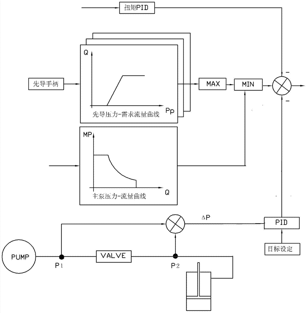
[0028] Such as figure 2 The embodiment of the present invention is shown in an excavator with a positive flow control hydraulic system energy-saving control method. ...


PUM


Abstract

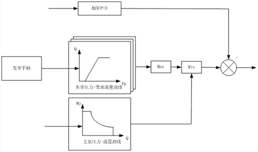
The invention discloses an energy-saving control method for a positive flow control hydraulic system, and belongs to the field of mechanical control. The energy-saving control method is suitable for the positive flow control hydraulic system and includes the steps that a precursor requirement flow is calculated according to a plurality of signals of a precursor handle; the maximum flow of a main pump is calculated according to signals of the main pump; the torque load control amount is output in a PID mode according to the stall value of an engine; the upstream and downstream differential pressure of a valve element is calculated according to upstream pressure and downstream pressure of the valve element and output in a PID mode to serve as the valve element load control amount; the smaller value of the precursor requirement flow and the maximum flow of the main pump serves as a control flow, and the control flow minus the torque load control amount and the valve element load control amount to serve as the final output flow. According to the technical scheme, the match between the discharge capacity and opening characteristics of the valve element is optimized, press loss of the valve element is reduced, and the energy-saving effect is achieved.

Description

technical field [0001] The invention belongs to the field of mechanical equipment control, and relates to an energy-saving control method, in particular to an energy-saving control method suitable for positive flow control hydraulic systems. Background technique [0002] As the hydraulic power output source of the hydraulic excavator, the hydraulic pump is an extremely important component of the excavator. In order to cooperate with the efficient and stable operation of the entire hydraulic system, the control mode of the hydraulic pump in the prior art generally adopts the electro-hydraulic comprehensive control mode. The electrical control system collects various control and feedback signals, makes judgments and controls the output of the hydraulic pump displacement through the proportional valve. Positive flow control hydraulic systems are one such system. [0003] Such as figure 1 The basic principle of flow control in a positive flow control hydraulic system is shown...

Claims


Application Information

Patent Timeline
Patent Type & Authority Applications(China)
IPC IPC(8): E02F9/22
Inventor 曹东辉罗树友石向星张俊涛
Owner SHANGHAI SANY HEAVY IND
Learn More