Water plugging pipe column suitable for small partitioning layer plug bottom water well and water plugging method

A technology of interlayer and water pipe, which is applied in the direction of earthwork drilling, sealing/isolation, wellbore/well components, etc. It can solve the problems of reducing oil well pump inspection cycle, leakage of lateral single retaining valve and failure of pressure, and failure of packer. Problems such as setting and sealing can be achieved to improve the success rate of construction, broaden application prospects and reduce the risk of well jamming

Inactive Publication Date: 2014-05-07
PETROCHINA CO LTD
View PDF8 Cites 2 Cited by
  • Summary
  • Abstract
  • Description
  • Claims
  • Application Information

AI Technical Summary

Problems solved by technology

However, the chemical method of injecting gel measures is costly and has a short validity period; the measure of ash squeezing is likely to cause oil layer pollution. Therefore, at present, the method of lowering bridge plugs is mostly used
[0003] However, for high water-cut oil reservoirs with small interlayers, conventional techniques such as bridge plug packers cannot meet the delamination requirements due to the small interlayers. The process string composed of a hand-off slip packer connected by tubing, a lateral single retention valve, a long rubber cartridge packer, and a plug is used for production. However, the following problems are often found when this technology is implemented on site: the existing lateral When the lateral single-retention valve is set in the pipe string, it often occurs that the leakage of the lateral single-retention valve does not cause pressure, and the packer is not set to affect the success rate of the process. Moreover, when the oil well produces sand and buries the fluid channel, it will Reduce the pump inspection cycle of the oil well. In addition, the packer must be lowered to the upper part of the oil layer, which affects the depth of the lower pump

Method used


Image

  • Water plugging pipe column suitable for small partitioning layer plug bottom water well and water plugging method

Examples


Embodiment Construction

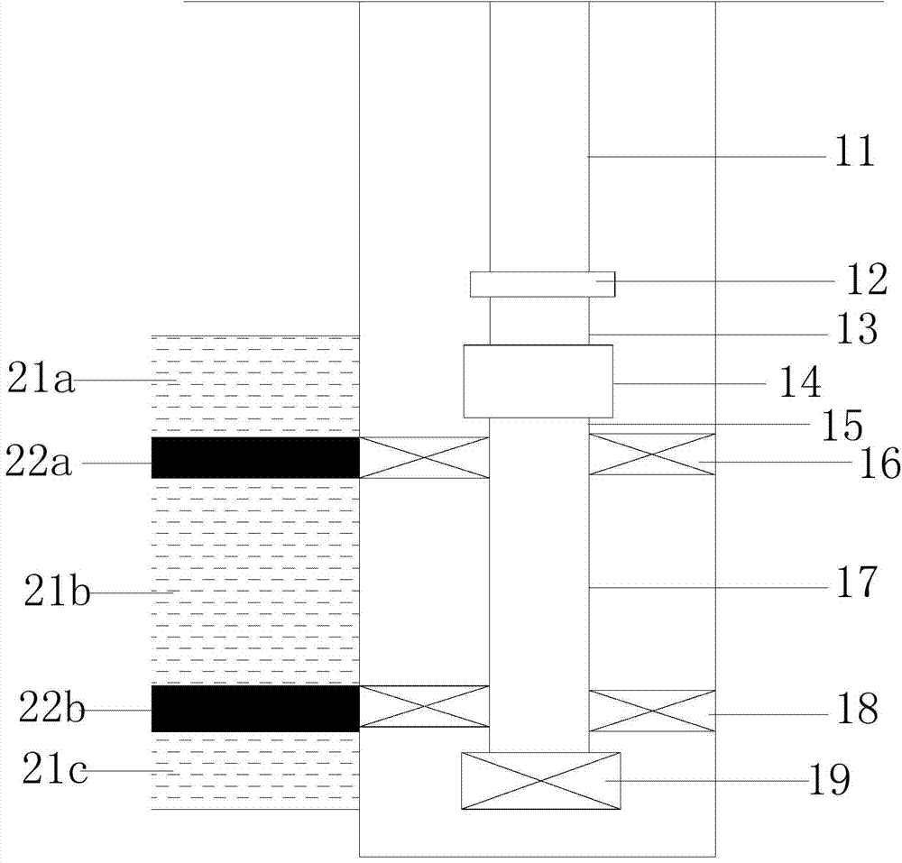
[0022] The invention provides a water plugging pipe string suitable for blocking the bottom of a water well in a small compartment, which includes a first oil pipe, a hydraulic hand-off tool, a second oil pipe, a positioning nipple, a third oil pipe, a hydraulic sealing Spacer, fourth tubing, long rubber cartridge packer and plug.

[0023] The present invention also proposes a water shutoff method using the above water shutoff string, the water shutoff method includes: lowering the water shutoff string into a designated position in the well, making the position of the hydraulic packer the same as the upper barrier in the well. Corresponding, and the position of the long rubber tube packer corresponds to the lower interlayer in the downhole, wherein the upper interlayer is located between the upper oil layer and the middle oil layer in the downhole, and the lower interlayer is located between the middle oil layer and the lower oil layer Inject fluid from the wellhead into the w...


PUM


Abstract

The invention provides a water plugging pipe column suitable for a small partitioning layer plug bottom water well and a water plugging method. The water plugging pipe column comprises a first oil pipe, a hydraulic releasing tool, a second oil pipe, a locating short section, a third oil pipe, a hydraulic packer, a fourth oil pipe, a long rubber cylinder packer and a screwed plug which are connected in sequence. The water plugging method comprises the steps that the water plugging column goes down to an appointed position in the well, so that the position of the hydraulic packer and an upper partitioning layer correspond, the position of the long rubber cylinder packer and a lower partitioning layer correspond, the upper partitioning layer is placed between an upper oil layer and a middle oil layer, the lower partitioning layer is placed between the middle oil layer and a lower oil layer, liquid is injected into the water plugging pipe column from a well opening and is pressurized to reach a first pressure value, the hydraulic packer and the side wall of the upper partitioning layer are subjected to corresponding setting, the long rubber cylinder packer is set on the side wall of the lower partitioning layer, liquid is continuously injected into the water plugging pipe column from the well opening and is pressurized to reach a second pressure value, so that the upper portion and the lower portion of the hydraulic releasing tool are separated, the upper portion of the tool is taken from the well along with the first oil pipe, and the first pressure value is smaller than the second pressure value.

Description

technical field [0001] The invention belongs to the field of petroleum exploitation, and in particular relates to a water shutoff pipe string and a water shutoff method suitable for a water well with a small interlayer to stop the bottom. Background technique [0002] In oil production, once the water cone enters the wellbore in the bottom water reservoir, the water cut in the oil well will inevitably rise, the economic benefit will deteriorate, and some wells will even be shut down due to high water cut. In order to achieve the purpose of controlling the bottom water, various attempts have been made in the development practice, such as perforating as far as possible from the oil-water interface, using chemical methods to inject gel, squeezing ash or lowering bridge plugs, etc., to control the production rate and production. However, the cost of injecting gel by chemical method is high, and the effective period is short; the measure of ash squeezing is easy to cause oil laye...

Claims


Application Information

Patent Timeline
Patent Type & Authority Applications(China)
IPC IPC(8): E21B33/127
Inventor 寇微麻德玉裴红史策赵圣琦刘欢赵树伟王丽莉陈晓毅
Owner PETROCHINA CO LTD
Why Eureka
Try Eureka