A magneto-rheological valve structure with three-dimensional helical flow channel

A three-dimensional spiral and liquid flow channel technology, applied in the field of hydraulic control valves, can solve the problems of low working voltage, small shear yield stress and high working voltage, and achieve the effects of saving energy, increasing the length of the flow channel, and increasing the pressure difference.

Inactive Publication Date: 2015-10-28
HEILONGJIANG UNIVERSITY OF SCIENCE AND TECHNOLOGY
View PDF5 Cites 0 Cited by
  • Summary
  • Abstract
  • Description
  • Claims
  • Application Information

AI Technical Summary

Problems solved by technology

Compared with magnetorheological fluid, electrorheological fluid has defects such as small shear yield stress and high working voltage required, while magnetorheological fluid has large yield stress, fast response, low working voltage and insensitivity to pollution

Method used


Image

  • A magneto-rheological valve structure with three-dimensional helical flow channel
  • A magneto-rheological valve structure with three-dimensional helical flow channel
  • A magneto-rheological valve structure with three-dimensional helical flow channel

Examples


Embodiment Construction

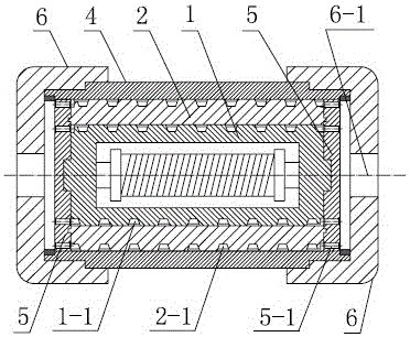
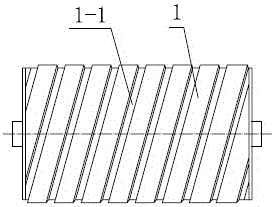
[0012] Referring to the accompanying drawings, a magneto-rheological valve structure of a three-dimensional spiral liquid flow channel includes a valve body 4, a valve body end cover 6, an oil inlet and outlet pan 5, an excitation coil 3 and a valve core part, and the valve core part includes: The inner guide tube 1, the outer guide tube 2, the excitation coil 3 are arranged in the inner guide tube 1, the outer guide tube 2 and the valve body 4 are in the shape of a ring, the inner guide tube 1, the outer guide tube 2 and the The valve body 4 is set on the coaxial line in turn, and on the outer circles of the inner guide tube 1 and the outer guide tube 2, there are respectively provided with an inner three-dimensional spiral flow groove 1-1 and an outer three-dimensional spiral flow groove 2-1, The inner three-dimensional spiral liquid flow channel 1-1 and the inner wall of the outer guide tube 2, the outer three-dimensional spiral liquid flow groove 2-1 and the inner wall of t...


PUM


Abstract

The invention discloses a magneto-rheological valve structure with three-dimensional spiral liquid flow channels. The aims of lengthening the lengths of the magneto-rheological flow channels and obtaining the large differential pressure are achieved. A valve element part in the structure comprises an inner flow guiding cylinder and an outer flow guiding cylinder, a magnet exciting coil is arranged in the inner flow guiding cylinder, the outer flow guiding cylinder and a valve body are of circular ring shapes, the inner flow guiding cylinder, the outer flow guiding cylinder and the valve body are sequentially installed in a sleeved mode, an inner three-dimensional spiral liquid flowing groove and an outer three-dimensional spiral liquid flowing groove are formed in the outer circle of the inner flow guiding cylinder and the outer circle of the outer flow guiding cylinder, the spiral flow channels are formed by the inner three-dimensional spiral liquid flowing groove and the inner wall of the outer flow guiding cylinder and formed by the outer three-dimensional spiral liquid flowing groove and the inner wall of the valve body, oil inlet-outlet discs are arranged on the end faces of the inner flow guiding cylinder and the end faces of the outer flow guiding cylinder, two sets of oil holes are formed in each oil inlet-outlet disc, the oil holes are communicated with the inner three-dimensional spiral liquid flowing groove and the outer three-dimensional spiral liquid flowing groove respectively, the valve body is arranged in valve body end covers, and oil holes in the valve body end covers are communicated with the oil holes in the oil inlet-outlet discs in the valve body. The magneto-rheological valve structure has the advantages that the length of an electromagnetic rheological path is lengthened, the use rate of magnetic force lines is improved, energy is saved, and the size of a magneto-rheological valve is reduced.

Description

Technical field [0001] The invention relates to a hydraulic control valve, in particular to the improvement of a magneto-rheological valve liquid flow channel, in particular to a magneto-rheological valve structure of a three-dimensional spiral liquid flow channel. Background technique [0002] Due to the existence of moving mechanical parts, traditional hydraulic control valves have complex structures, high processing requirements, and are easy to wear, resulting in unreliable movement, large volume, high cost, and problems such as difficult control, slow response, and loud working noise. With the development of mechatronics technology and the widespread application of computers, especially the emergence of controllable fluids (rheological fluids and magnetorheological fluids), people began to turn their attention to hydraulic servo systems based on controllable fluids. Compared with magnetorheological fluid, electrorheological fluid has defects such as small shear yield st...

Claims


Application Information

Patent Timeline
Patent Type & Authority Patents(China)
IPC IPC(8): F15B13/02
Inventor 刘丹丹赵灿汤春瑞李忠勤张桂凤郭智波郭智涛
Owner HEILONGJIANG UNIVERSITY OF SCIENCE AND TECHNOLOGY
Why Eureka
Try Eureka