
Overload protection valve and overload valve with overload protection valve

A technology of overload protection valve and valve sleeve, applied in the direction of fluid pressure actuating device, fluid pressure actuating system safety, mechanical equipment, etc., can solve the problem of overload safety valve not having, being damaged by controlled parts, increasing enterprise cost, etc. To achieve the effect of improving the opening and closing performance, prolonging the service life and speeding up the processing speed

Active Publication Date: 2016-09-14
蚌埠行时知识产权运营有限公司
View PDF9 Cites 0 Cited by
  • Summary
  • Abstract
  • Description
  • Claims
  • Application Information

AI Technical Summary

Problems solved by technology

[0003] In order to solve the problem that the overflow speed is slow or unable to work when the medium-load safety valve in the prior art is working, resulting in damage to the controlled components, resulting in large economic losses and safety accidents
At the same time, in order to solve the problem that the overload safety valve does not have the function of replenishing oil to the large cavity of the system, it needs external assistance to replenish oil, consumes energy, and increases the cost of the enterprise

Method used


Image

  • Overload protection valve and overload valve with overload protection valve
  • Overload protection valve and overload valve with overload protection valve
  • Overload protection valve and overload valve with overload protection valve

Examples


Embodiment Construction

[0026] The present invention will be further described below in conjunction with the accompanying drawings.

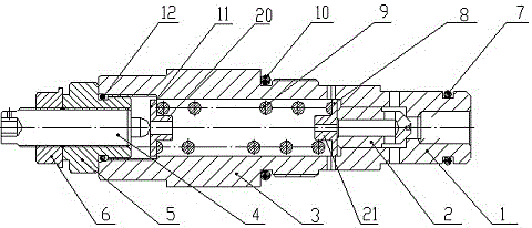
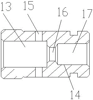
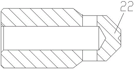
[0027] As shown in the figure, an overload protection valve includes a valve sleeve 1, a valve core 2, a valve sleeve seat 3, a pressure regulating screw 4, a pressure regulating valve seat 5, and a lock nut 6. In order to improve the sealing performance of the overload valve, A sealing ring 7 is provided outside the valve sleeve 1 , a sealing ring 10 is provided outside the valve sleeve seat 3 , and a sealing ring 12 is provided outside the pressure regulating valve seat 5 . The valve sleeve seat 3 is connected to the rear end of the valve sleeve 1. In order to improve the processing speed and processing accuracy of the two, the valve sleeve 1 and the valve sleeve seat 3 are processed separately, and the rear end of the valve sleeve 1 and the front end of the valve sleeve seat 3 are made of Snap connection. The front end of the pressure regulating valve seat 5 is pro...


PUM


Abstract

The invention discloses an overload protective valve and an overload valve comprising the overload protective valve and relates to the technical field of engineering machinery. The overload protective valve comprises a valve sleeve and a pressure-regulating lead screw. The overload protective valve is characterized in that the rear end of the valve sleeve is connected with a valve sleeve base, the front end of a pressure-regulating valve seat is provided with external threads, the front end of the pressure-regulating valve seat is connected and fixed to the inner side of the rear end of the valve sleeve seat through the threads, and the pressure-regulating lead screw penetrates through the pressure-regulating valve seat to extend into the valve sleeve seat; a spring is arranged on the inner side of the valve sleeve seat between a valve element and the pressure-regulating valve seat. The overload protective valve aims to solve the problems that in the prior art, when an overload relief valve operates, the overflowing speed is low or operation fails, so that a controlled component is damaged, and the problem that the overload relief valve cannot replenish oil to a large cavity of the system, so that oil replenishment needs external assistance and the enterprise cost is increased is solved at the same time. The overload protective valve has the advantages of being simple in structure, good in opening and closing performance, high in overflowing speed, long in service life, capable of conducting oil replenishment work and the like. The invention further provides the overload valve comprising the overload protective valve.

Description

technical field [0001] The invention relates to the technical field of engineering machinery, in particular to an overload protection valve and an overload valve including the overload protection valve. Background technique [0002] The hydraulic valve is an automatic component operated by pressure oil. It is controlled by the pressure oil of the pressure distribution valve. It is usually used in combination with the electromagnetic pressure distribution valve. It can be used to remotely control the on-off of the oil, gas and water pipeline system of the hydropower station. Among them, the one used to control the pressure is also called the pressure control valve. The relief valve in the pressure control valve can control the hydraulic system to maintain a constant state when it reaches the set pressure. The overflow valve used for overload protection is called overload safety valve. When the system fails and the pressure rises to the limit value that may cause damage, the ...

Claims


Application Information

Patent Timeline
Patent Type & Authority Patents(China)
IPC IPC(8): F15B20/00
Inventor 赵文荣
Owner 蚌埠行时知识产权运营有限公司
Learn More