Multi-flame burner and method for heating a workpiece

A burner and combustion head technology, which is applied in the combination of multiple burners, combustion methods, burners, etc., can solve the problems of expensive safety precautions and achieve the effects of weight reduction, less maintenance requirements, and low downtime

Inactive Publication Date: 2014-05-07
LINDE AG
View PDF11 Cites 3 Cited by
  • Summary
  • Abstract
  • Description
  • Claims
  • Application Information

AI Technical Summary

Problems solved by technology

Proper security precautions are expensive

Method used


Image

  • Multi-flame burner and method for heating a workpiece
  • Multi-flame burner and method for heating a workpiece
  • Multi-flame burner and method for heating a workpiece

Examples


Embodiment Construction

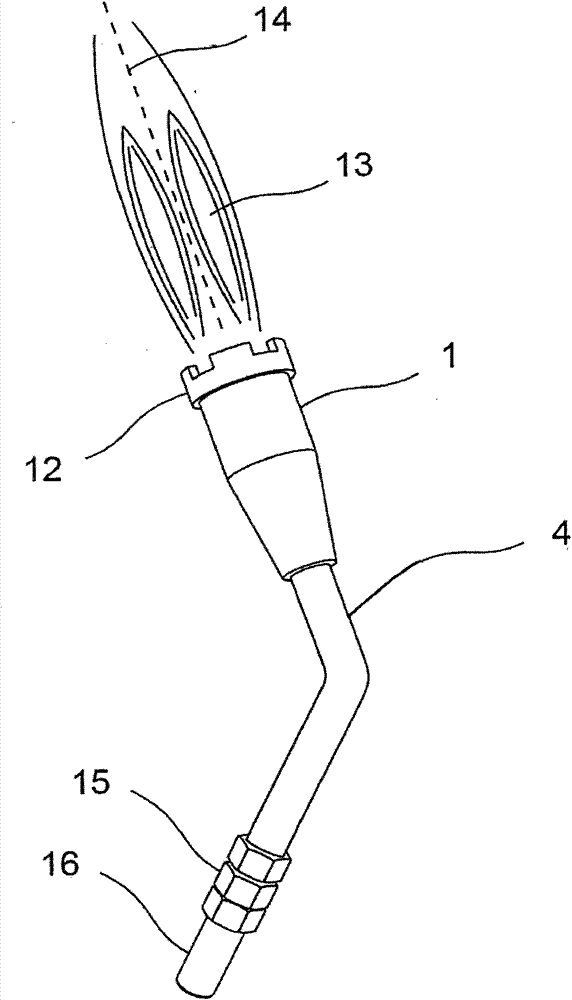
[0045] figure 1 A schematic view of a combustion head 1 is shown with a nozzle ring 12 which can have any desired number of preferably centrally arranged nozzles through which fuel can escape. Ignition of the fuel produces a combustion flame 13 which extends along a flame axis 14 . Via an offset connecting pipe 4 together with a threaded joint 15 and a connecting nozzle 16, the combustion head 1 can be connected to the feed line. For example, the connection nozzle 16 is welded to the feed line.

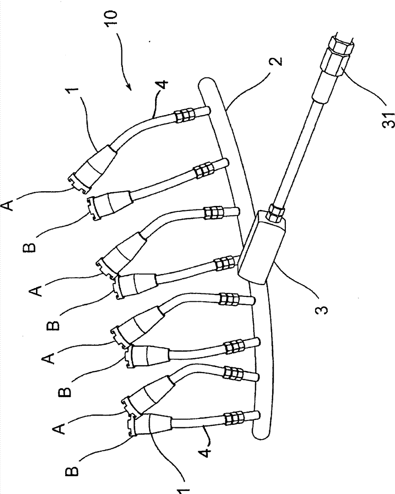
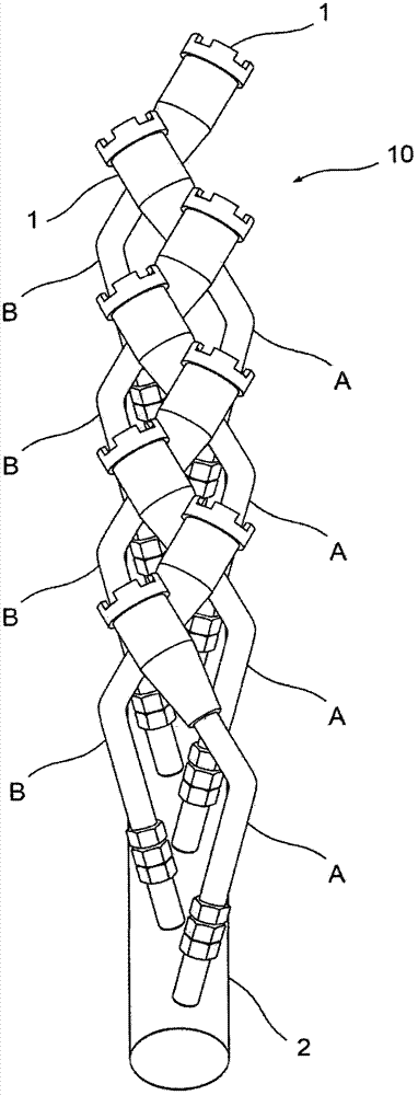
[0046] figure 2 A schematic side view of a multi-flame burner, generally designated 10 , according to a particularly preferred embodiment of the present invention is shown. The multi-flame burner 10 comprises a total of eight combustion heads 1, each of which is accompanied by a respective offset connecting pipe 4, not all of which are provided with a reference number. The combustion heads 1 are here combined into groups A and B of combustion heads. The combustion heads A of the...


PUM


Abstract

A multi-flame burner includes burner heads which are set up to generate at least one burner flame directed along a respective flame axis when supplied with a fuel, wherein the flame axes of respectively adjacent burner heads are inclined relative to each other. A method for preheating a workpiece, in particular a pipe or large-diameter pipe, is provided.

Description

technical field [0001] The present invention relates to a multi-flame burner having a combustion head and accompanying connecting pipes, said combustion head being arranged to produce at least one combustion flame directed along a respective flame axis when fuel is supplied, and to a multi-flame burner with corresponding A multi-flame burner preheating method for workpieces, especially for preheating pipes or large diameter pipes. Background technique [0002] Workpieces must be preheated within a very wide range of material handling and manufacturing processes. The invention here draws first and foremost on preheating in welding operations. However, the invention can also be used per se in other methods that require the introduction of heat by means of a flame. [0003] In known welding processes, the workpieces to be welded are preheated for various reasons. The main hazard of lack of preheating is hydrogen embrittlement in the so-called heat-affected zone. In addition...

Claims


Application Information

Patent Timeline
Patent Type & Authority Applications(China)
IPC IPC(8): F23D14/38
CPCB23K5/02F23D21/005F23C5/08F23D14/38F23D23/00B23K9/235F23D91/02
Inventor J·斯托克
Owner LINDE AG
Why Eureka
Try Eureka