A small drying box

A drying oven, small technology, applied in dryer combination, drying solid materials, drying and other directions, can solve the problems of single material placement, uneven drying, low quality, etc., to achieve good material quality, convenient material drying, volume small effect

Inactive Publication Date: 2015-11-25
SOUTHWEST UNIVERSITY
View PDF6 Cites 0 Cited by
  • Summary
  • Abstract
  • Description
  • Claims
  • Application Information

AI Technical Summary

Problems solved by technology

[0005] The purpose of the present invention is to provide a small drying box which adopts the combination of rotating loading tray and shelf for placing materials, so as to solve the problems of single material placing, uneven drying, low quality and high energy consumption in existing small drying boxes. question

Method used


Image

  • A small drying box
  • A small drying box
  • A small drying box

Examples


Embodiment Construction

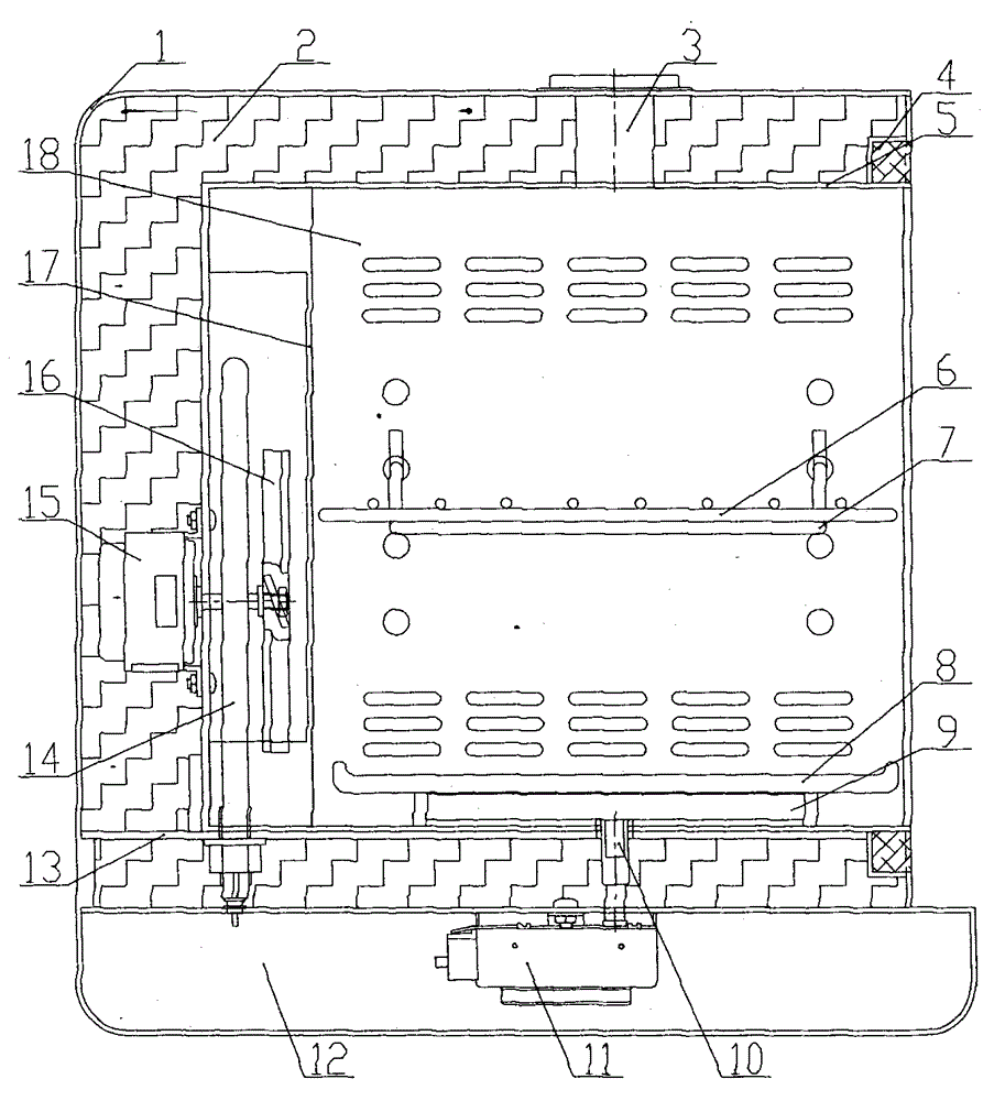
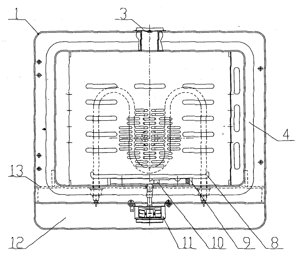
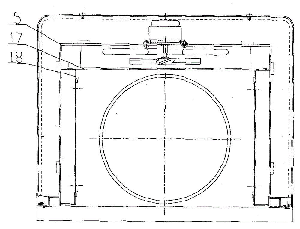
[0022] combine figure 1 , figure 2 , image 3 and Figure 4 , The small drying box of the present invention includes a drying box body 1 and a drying chamber 5 for drying materials. The heat insulating material 2 is filled between the drying box body 1 and the drying cavity 5 .

[0023] The drying box 1 includes a drying chamber 5 , a carrying plate 13 , a driving motor 11 , and an electric control box 12 . The upper side of the drying box 1 is provided with an exhaust hole 3 through which the humid air is discharged. The drying chamber 5 is installed above the carrier plate 13 and fixed by positioning pins on the carrier plate 13; the driving motor 11 and the electric control Casing 12 is installed on the bottom of drying box body 1, and drive motor 11 is fixed on the drying box body 1 by bolt, and the vertical rotating shaft of drive motor 11 enters in the drying cavity 5 through the inner plate of drying box body 1 and carrying plate 13.

[0024] The drying chamber 5 ...


PUM


Abstract

The invention discloses a small drying box, and relates to the technical field of drying machines. The small drying box is characterized by being composed of a drying box body, a drying cavity, an exhaust hole, a bearing plate, an electric heater, a fan, a driving motor, a back plate, side plates, an object carrying tray, a shelf, an electric control box and the like. The bearing plate is arranged in the drying box body, the drying cavity is formed above the bearing plate, and the driving motor and the electric control box are arranged below the drying box body. A vertical rotary shaft of the driving motor penetrates through an inner plate of the drying box body and the bearing plate to enter the drying cavity and is connected with the object carrying tray. The electric heater and the fan are fixed to the back portion of the drying cavity. The back plate, the side plates and the shelf are arranged in the drying cavity. The exhaust hole is formed in the top of the drying box body. The electric heater, the fan and the driving motor are controlled by a control circuit in the electric control box. Two material containing modes are provided, and the problem that the small drying box carries out drying unevenly can be solved. The small drying box has the advantages of being small in size, convenient to operate, low in cost and the like, and is suitable for drying materials in homes and laboratories.

Description

technical field [0001] The invention relates to a drying machine, in particular to a small drying box which adopts the combination of two material placement methods of a rotating loading tray and a shelf. Background technique [0002] With the improvement of people's living standards, people's requirements for food quality have also increased, but they will inevitably encounter some problems in life: most agricultural products and various foods need to be stored with lower moisture, but due to the moisture content of the product itself If there is too much water, or due to the humid environment and some human factors, the product has a high water content, and the product will quickly rot or deteriorate. [0003] my country's food drying machinery has a history of decades of development, but most of them are used for production. The users are mainly farms, grain depots and food production bases. They are mainly used in factory workshops, warehouses, material reserves, food an...

Claims


Application Information

Patent Timeline
Patent Type & Authority Patents(China)
IPC IPC(8): F26B20/00F26B23/04F26B25/00
Inventor 杨玲刘斌杨明金郭孟报牛坡
Owner SOUTHWEST UNIVERSITY
Why Eureka
Try Eureka