Eureka AIR delivers breakthrough ideas for toughest innovation challenges, trusted by R&D personnel around the world.

Arrayed micro gas chromatographic column chip with super-large contact area

A micro-gas chromatography and chip technology, applied in the field of chromatographic analysis, can solve problems such as difficult separation, small attachment surface area, and limited ability of chromatographic columns to separate components, and achieve the effect of improving the ability and increasing the attachment area

Inactive Publication Date: 2014-05-07
INST OF ELECTRONICS CHINESE ACAD OF SCI
View PDF11 Cites 18 Cited by
  • Summary
  • Abstract
  • Description
  • Claims
  • Application Information

AI Technical Summary

Problems solved by technology

[0004] However, the existing miniature gas chromatographic column chips are limited in size due to the limited length of the chromatographic column. Therefore, the attachment surface area of ​​the stationary phase in the channel of the chromatographic column is relatively small, which limits the full contact between the mixed gas and the stationary phase; On the other hand, the micro-columns with empty channels have relatively large changes in the pressure and air velocity in the channel, and the pressure and flow velocity are important factors affecting the separation performance of the chromatographic column.
Therefore, the above unfavorable factors limit the ability of the chromatographic column to separate components, especially for those complex mixtures, the separation is even more difficult, greatly reducing the response ability to low-concentration samples, and restricting the detection of the detector. limit

Method used


Image

  • Arrayed micro gas chromatographic column chip with super-large contact area
  • Arrayed micro gas chromatographic column chip with super-large contact area
  • Arrayed micro gas chromatographic column chip with super-large contact area

Examples


Embodiment Construction

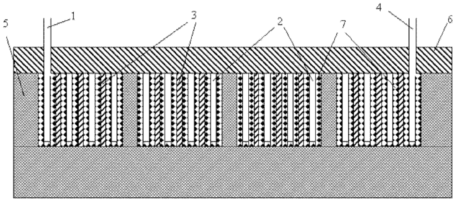
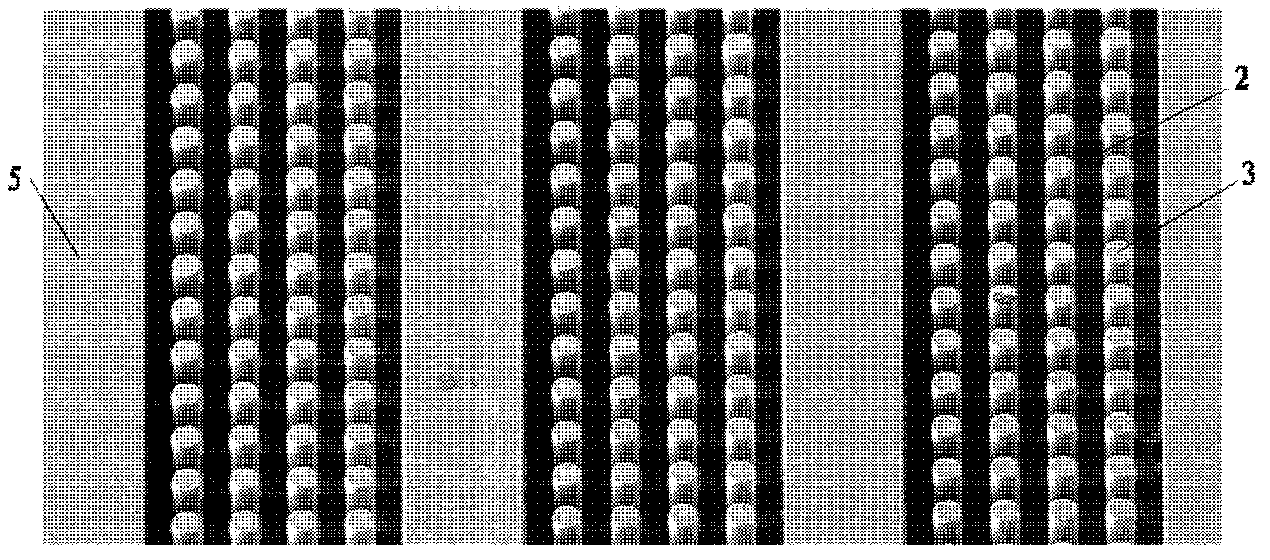
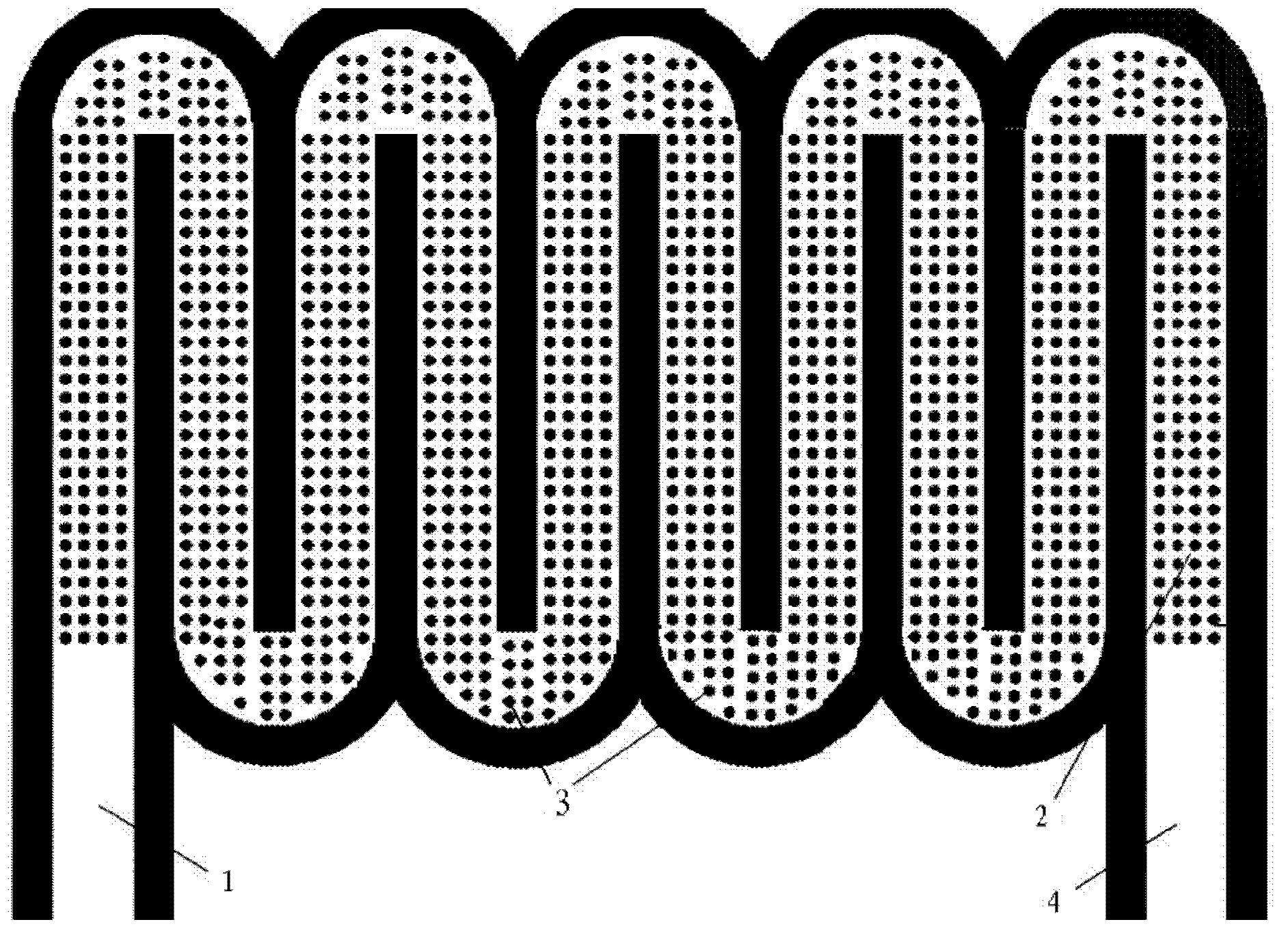
[0029] The present invention proposes an arrayed micro-gas chromatographic column chip with an ultra-large contact area. By setting arrayed columns in the channel of the micro-gas chromatographic column, and through electrochemical corrosion, the surface of the micro-gas chromatographic column channel and the array A layer of porous silicon is grown on the surface of the chemical column. Because the structure of porous silicon is loose and porous, its surface area increases by tens of thousands of times. Therefore, fixing the stationary phase on the surface of porous silicon can greatly increase the attachment of the stationary phase in the chromatographic column. area.

[0030] In order to make the object, technical solution and advantages of the present invention clearer, the arrayed micro gas chromatography column chip with super large contact area and its preparation method of the present invention will be described in detail below in conjunction with specific examples and ...


PUM


Abstract

The invention discloses an arrayed micro gas chromatographic column chip with a super-large contact area. The chip comprises a silicon substrate (5), channels (2) and arrayed vertical pillars (3) processed on the silicon substrate (5), the arrayed vertical pillars (3) are distributed in the channels (2), a layer of porous silicon (7) grows on the surface of each of the channels (2) and the arrayed vertical pillars (3) through an electrochemical corrosion method after the arrayed vertical pillars (3) and the channels (2) are processed, and the surface of the porous silicon (7) is fixed with a stationary phase. The chip comprises a sealing layer (6) sealing the channels (2) on the silicon substrate (5) in a bonding manner. The porous silicon of the chip has a loose and porous structure, so the surface area of the chip increases thousands of times; and the surface of the porous silicon is fixed with the stationary phase, so the bonding area of the stationary phase in the chromatographic column can be greatly increased, and is 5-10 times higher than that the bonding area of the stationary phase in a chromatographic column having an empty channel structure. The change of the speed and the pressure of a gas flow in channels having the above structure is much smaller than the change of the speed and the pressure of a gas flow in chromatographic columns having the empty channel structure, so the mixed gas separation capability is greatly improved.

Description

technical field [0001] The invention belongs to the technical field of chromatographic analysis, and in particular relates to an arrayed micro-gas chromatography column chip with a super large contact area and a manufacturing method thereof. The invention is suitable for the separation of mixed gases and can be applied to field environmental monitoring, biochemical warfare agents, and food Safety, drug detection, early diagnosis of cancer, etc. Background technique [0002] The gas chromatographic column is one of the key components of the chromatographic analysis system, and its function is to realize the separation of mixed gases. Traditional gas chromatographic analysis systems mostly use packed columns or capillary columns, which are usually relatively long, occupy a relatively large volume space, and have a relatively slow analysis speed, making it difficult to meet the needs of on-site rapid analysis and detection. [0003] In order to meet the needs of on-site analys...

Claims


Application Information

Patent Timeline
IPC IPC(8): G01N30/60
Inventor 崔大付孙建海陈兴张璐璐蔡浩原任艳飞李辉
Owner INST OF ELECTRONICS CHINESE ACAD OF SCI
Why Eureka
Eureka Blog
Learn More