Multi-mode interference optical switch with controlled input position and preparation method of multi-mode interference optical switch
A technology of multi-mode interference and input position, applied in the coupling of optical waveguides, etc., can solve the problems of difficult manufacturing process, high cost, complex structure, etc., and achieve simple structure and modulation method, low nonlinearity, and low process difficulty. Effect
- Summary
- Abstract
- Description
- Claims
- Application Information
AI Technical Summary
Problems solved by technology
Method used
Image
Examples
Embodiment
[0046] Embodiment: 1×4 multi-mode interference type optical switch.
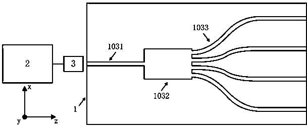
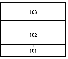
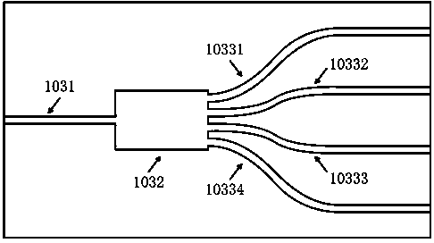
[0047] Such as figure 1 As shown, an input position controlled multi-mode interference optical switch of the present invention includes a planar light wave optical circuit chip 1 , a light source 2 , an input optical fiber array 3 and an electric automatic core adjustment device 4 . The planar lightwave optical circuit chip 1 includes a silicon substrate 101 , a silicon dioxide buffer layer 102 grown on the silicon substrate 101 , a waveguide 103 grown on the silicon dioxide buffer layer 102 , and a cladding layer 104 grown on the waveguide 103 . The waveguide 103 includes an input-stage single-mode waveguide 1031 , an intermediate-stage multi-mode waveguide 1032 and four output-stage single-mode waveguides 1033 . The light source 2 is connected to the input end of the input fiber array 3, the output end of the input fiber array 3 is connected to the input end of the input-stage single-mode waveguide 1031,...
PUM
 Abstract
Description
Claims
Application Information
 - R&D
- Intellectual Property
- Life Sciences
- Materials
- Tech Scout
- Unparalleled Data Quality
- Higher Quality Content
- 60% Fewer Hallucinations
Browse by: Latest US Patents, China's latest patents, Technical Efficacy Thesaurus, Application Domain, Technology Topic, Popular Technical Reports.
© 2025 PatSnap. All rights reserved.Legal|Privacy policy|Modern Slavery Act Transparency Statement|Sitemap|About US| Contact US: help@patsnap.com


