
Method for manufacturing micro model of real rock core, and used grinding holder and adhesive

A technology of microscopic model and real rock core, which is applied in grinding holders and adhesives, making high-definition real rock core micromodels, and ultra-thin fields, which can solve the problems of low simulation degree, low imaging resolution, and reduced imaging resolution, etc. problem, to achieve the effect of clear boundary and high imaging definition

Active Publication Date: 2014-05-07
CHINA PETROLEUM & CHEM CORP +1
View PDF8 Cites 11 Cited by
  • Summary
  • Abstract
  • Description
  • Claims
  • Application Information

AI Technical Summary

Problems solved by technology

[0005] Main disadvantages: using hydrofluoric acid etching technology, the minimum throat can only be controlled at 50-80 microns, the size of the pore throat is too large, and the degree of simulation is low. In addition, there are differences between glass and rock particles, which cannot simulate the original appearance of the core. The experimental results are convincing Poor strength
[0008] Main disadvantages: Although the original appearance of the real core is maintained, the thickness of the core slice is at the millimeter level. Under the microscope, the layer of rock particles is seriously superimposed, and the imaging resolution is low. The boundary between crude oil and rock particles is not clear, and it is impossible to clearly observe the pore-level oil displacement. the whole process
In addition, although the models all have good surface smoothness, the adhesive (epoxy resin) used to fix the rock slices affects its light transmission and reduces the imaging clarity
Although the latter makes up for the lack of core simulation of the former, it is far behind the former in terms of imaging clarity

Method used


Image

  • Method for manufacturing micro model of real rock core, and used grinding holder and adhesive
  • Method for manufacturing micro model of real rock core, and used grinding holder and adhesive

Examples


Embodiment 1

[0031] The real rock core micro model making method comprises the following steps:

[0032] 1) Select the cylindrical core for the experiment, measure and record the permeability and porosity;

[0033] 2) Put the core into a glass tube, add an appropriate amount of rosin, and heat (>180°C) to saturate for 10 hours;

[0034] 3) Cool at room temperature, cut the core into 2~3mm thin slices with a diamond core slicer, smooth and clean the surface of the core, and do grinding pretreatment;

[0035] 4) After mixing cyanoacrylate and rosin in a ratio of 1:1, the core slices are glued and fixed on the chrome glass;

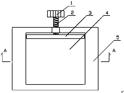
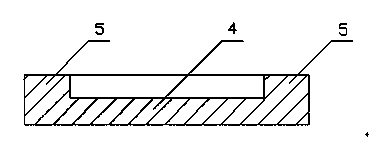
[0036] 5) Fix the chrome glass with the core slice attached to the grinding holder, grind the surface of the slice, first use coarse emery to rough grind on the grinder, and grind the specimen to a thickness of about 200 μm. After that, finely grind with fine emery to smooth and polish the surface. When the fine grinding reaches about 80μm~150μm, the sample is placed ...


PUM

PropertyMeasurementUnit
thicknessaaaaaaaaaa
thicknessaaaaaaaaaa
melting pointaaaaaaaaaa

Abstract

The invention belongs to petroleum exploitation technical field and especially relates to a method for manufacturing an ultrathin and high-definition micro model of a real rock core and a used grinding holder and adhesive in microcosmic simulating oil displacement technology in the field of increase in laboratory experiment recovery efficiency in petroleum industry. A rock core slice is directly bonded between two chromium plate glass layers by the rock core grinding holder and filling adhesive. A manufacturing process is controlled and the micro model of a real rock core is formed integrally. High-definition imaging is achieved on the basis of keeping the original pore structure of the real rock core. The method, the grinding holder and adhesive are mainly used in laboratory microcosmic simulating oil displacement experiments in petroleum industry and are suitable for researching permeability rules of underground fluid, such as petroleum and natural gas or the like, in a porous medium.

Description

technical field [0001] The invention belongs to the technical field of petroleum exploitation, in particular to an ultra-thin, high-definition real rock core micromodel manufacturing method and a grinding holder and an adhesive used in the microcosmic simulated oil displacement technology in the field of laboratory experiments in the petroleum industry to enhance oil recovery . Background technique [0002] At present, there are two types of microcosmic models used in the field of microcosmic simulation of oil displacement technology in laboratory experiments of enhanced oil recovery in the petroleum industry. [0003] 1. Microscopic seepage simulation model (patent number: 00109777) [0004] This technology uses a photochemical etching process to precisely photoetch the pore structure of natural rock core slices onto flat optical glass, which is etched with hydrofluoric acid and then sintered at high temperature to form it. [0005] Main disadvantages: using hydrofluoric ...

Claims


Application Information

Patent Timeline
Patent Type & Authority Applications(China)
IPC IPC(8): G09B23/40B24B37/27C09J4/04
Inventor 李奋陈亚宁孟小海陈霆耿建梅姚风英段红斌刘丽王曦刘津李继山
Owner CHINA PETROLEUM & CHEM CORP
Learn More