Friction nanometer generator

A nano-generator, friction layer technology, applied in the direction of triboelectric generators, etc., can solve the problems such as the inability to realize automatic separation and contact, the limitation of the range of receiving external mechanical energy, and the complex structure of the generator, which is beneficial to popularization and application, simplification Structure and preparation process, the effect of simple structure

Active Publication Date: 2014-05-07
BEIJING INST OF NANOENERGY & NANOSYST
View PDF4 Cites 71 Cited by
  • Summary
  • Abstract
  • Description
  • Claims
  • Application Information

AI Technical Summary

Problems solved by technology

However, in this triboelectric nanogenerator, two materials with different frictional properties are in contact with and separated from each other through an elastic separation material, and

Method used


Image

  • Friction nanometer generator
  • Friction nanometer generator
  • Friction nanometer generator

Examples


Embodiment 1

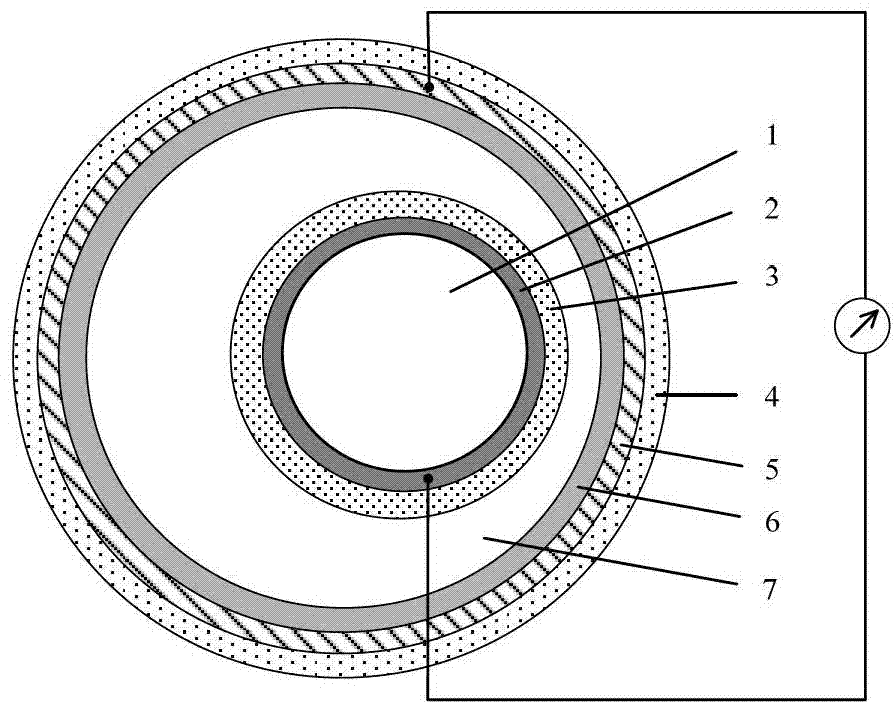
[0068] see figure 1 , a typical basic structure of the triboelectric nanogenerator of the present invention includes a casing and a core body, wherein the core body sequentially includes: an inner core 1, a first conductive layer 2 attached to the outer surface of the inner core 1 And the first friction layer 3 arranged in contact with the outer surface of the first conductive layer 2, the outer surface of the first friction layer 3 faces the cavity 7 of the housing; the housing includes in turn from the outside to the inside: the shell 4, attached to The second conductive layer 5 on the inner surface of the housing 4 and the second friction layer 6 are provided in contact with the inner surface of the second conductive layer 5 , and the inner surface of the second friction layer 6 faces the cavity 7 . The triboelectric nanogenerator structure also includes electrode lead wires that are necessarily related to the triboelectric nanogenerator structure, and are used to lead out ...

Embodiment 2

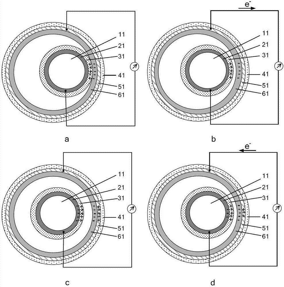
[0092] In the first embodiment, the first friction layer 3 and the second friction layer 6 of the triboelectric nanogenerator are continuous structures, and the difference between this embodiment and the first embodiment is only that the first friction layer and the second friction layer have at least One is a discontinuous structure, that is, the first friction layer includes a plurality of first friction units that are not connected to each other, and / or the second friction layer includes a plurality of second friction units that are not connected to each other. The materials of each part of the generator can be exactly the same as those in the first embodiment.

[0093] In the present invention, the first conductive layer is the electrode layer of the first friction layer, and the second conductive layer is the electrode layer of the second friction layer. Therefore, in this embodiment, the first friction layer includes Correspondingly, the first conductive layer also inclu...

Embodiment 3

[0103] In the second embodiment, the movement of the core in the casing is not restricted, and can move in any direction in three-dimensional space. The difference between this embodiment and the second embodiment is that the core can only move in one dimension in the housing. The materials of each part of the generator can be exactly the same as those in the first or second embodiment.

[0104] see Image 6 , the generator includes a shell and a core placed in the cavity of the shell, wherein the inner core 14 of the core is a cylinder, and the upper and lower surfaces of the inner core 14 are respectively provided with first conductive units 241 and 242. The first friction units 341 and 342 are arranged in contact with the conductive units 241 and 242 respectively; the structure surrounded by the inner surface of the shell 44 of the housing is also a cylinder, and the second conductive units are respectively arranged on the upper and lower bottom surfaces of the inner surfa...


PUM

PropertyMeasurementUnit
Thicknessaaaaaaaaaa

Abstract

This invention provides a friction nanometer generator, comprising a housing and an core body which is positioned within a cavity of the housing and can move freely. The core body, from the inside to the outside, successively comprises an inner core, a first conducting layer attached on the outer surface of the inner core and a first friction layer which is positioned on the outer surface of the first conducting layer in a contact manner. The outer surface of the first friction layer faces the cavity. The housing, from the outside to the inside, successively comprises a housing, a second conducting layer attached on the inner surface of the housing and a second friction layer which is positioned on the inner surface of the second conducting layer in a contact manner. The inner surface of the second friction layer faces the cavity. Under the action of the external force, the core body moves within the cavity, which enables the outer surface of the first friction layer to be contact with or separated from the inner surface of the second friction layer, and the first conducting layer and the second conducting layer can output electric signals to the external circuit. The friction nanometer generator disclosed by the invention is simple in structure and is wide in application.

Description

technical field [0001] The invention relates to the field of energy conversion, in particular to a friction nanogenerator capable of converting mechanical energy into electrical energy. Background technique [0002] Today, with the rapid development of microelectronics and material technology, a large number of new microelectronic devices with multiple functions and high integration have been developed continuously, and have shown unprecedented application prospects in various fields of people's daily life. However, the research on the power supply system matched with these microelectronic devices is relatively lagging behind. Generally speaking, the power supply of these microelectronic devices all comes from batteries directly or indirectly. Batteries are not only large in size and heavy in weight, but also contain toxic chemical substances that are potentially harmful to the environment and the human body. Therefore, it is of great significance to develop technologies th...

Claims


Application Information

Patent Timeline
IPC IPC(8): H02N1/04
CPCH02N1/04
Inventor 王中林杨亚
Owner BEIJING INST OF NANOENERGY & NANOSYST
Why Eureka
Try Eureka