Seal structure for fuel pump

A technology of sealing structure and fuel pump, which is applied in the direction of engine sealing, liquid fuel feeder, charging system, etc., can solve problems such as assembly problems, and achieve the effect of compact radial size and enlarged shape

Active Publication Date: 2014-05-07
HONDA MOTOR CO LTD
View PDF6 Cites 2 Cited by
  • Summary
  • Abstract
  • Description
  • Claims
  • Application Information

AI Technical Summary

Problems solved by technology

However, if the seals are only installed separately, the seals cannot be locked to the pump even if they are assembled to the pump. Therefore, it is necessary to pay attention not to drop the seals during assembly, which will cause a problem in assemblability.

Method used


Image

  • Seal structure for fuel pump
  • Seal structure for fuel pump
  • Seal structure for fuel pump

Examples


Embodiment Construction

[0036] Hereinafter, an embodiment of the present invention will be described with reference to the drawings. It should be noted that, in the description, descriptions of directions such as front, rear, left, right, and up and down mean that they are the same as directions relative to the vehicle body unless otherwise specified. In addition, the reference sign FR shown in each figure shows the front of a vehicle body, the reference sign UP shows the upper side of a vehicle body, and the reference sign L shows the left side of a vehicle body.

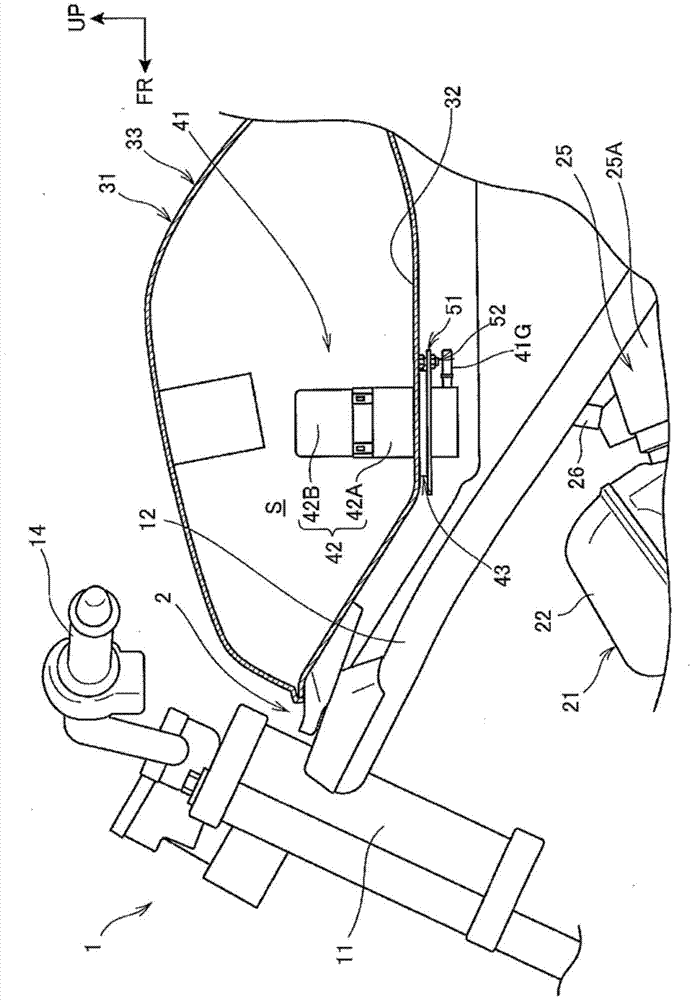
[0037] figure 1 The front part structure of the motorcycle to which the embodiment of this invention is applied is shown.

[0038] The frame 2 of the motorcycle 1 is a combination of various metal parts by welding or the like, including a head pipe 11, a pair of left and right main frames 12 extending backward and downward from the head pipe 11, and an engine 21 supported on the head pipe 11. The fuel tank 31 is supported behind the hea...


PUM


Abstract

Provided is a seal structure for a fuel pump having a double-seal construction of a separately provided outer seal and inner seal, with which it is possible to improve the ease with which both seals can be assembled, and with which it is possible to employ a compact installation area for the double seal. This double seal (71) is provided between a fuel pump insertion hole and a flange (43) of the fuel pump, and has an outer seal (72) and a separate inner seal (82). Outer seal inward protrusions (73) which protrude radially inward are provided on the outer seal (72), and inner seal outward protrusions (83) which protrude radially outward are provided on the inner seal (82), and slits (48, 49) are provided as positioning parts into which the respective protrusions (73, 83) fit. The protrusions (73, 83) are arranged alternately in the circumferential direction of the seals (72, 82), and are positioned within the same region in the radial direction.

Description

technical field [0001] The invention relates to a sealing structure of a fuel pump. A fuel pump insertion port is formed on a fuel tank storing fuel, and an annular double seal is arranged between the fuel pump insertion port and a flange provided on the fuel pump. Background technique [0002] As a sealing structure between a fuel tank and a fuel pump, an annular double seal is sometimes used in which an inner seal, an outer seal, and a connecting portion connecting the two seals are integrally formed (see, for example, Patent Document 1). The outer seal of the double seal has an annular concave portion with a cross-section in a k-shape on the outer periphery, and a concave portion wider and deeper than the peripheral concave portion is formed on the outer periphery of the connecting portion. According to such a structure, since the protrusion part above and below a recessed part bends, the air in a double seal space can be discharged easily, and sealing performance can be ...

Claims


Application Information

Patent Timeline
Patent Type & Authority Applications(China)
IPC IPC(8): F02M37/10F02M37/00F16J15/10
CPCB62J35/00F02M37/103F16J15/061
Inventor 上野正树堀内哲稻冈洋
Owner HONDA MOTOR CO LTD
Why Eureka
Try Eureka