Compressor

A compressor and compression mechanism technology, applied in the field of compressors, can solve the problems of compressor volume efficiency, compressor efficiency decrease, density decrease, etc., and achieve the effect of suppressing pressure loss and realizing high efficiency

Active Publication Date: 2014-05-07
PANASONIC CORP
View PDF5 Cites 5 Cited by
  • Summary
  • Abstract
  • Description
  • Claims
  • Application Information

AI Technical Summary

Problems solved by technology

Therefore, low-temperature sucked refrigerant gas is heated while passing through the suction hole 110, thereby causing a decrease in density, and a decrease in the volumetric efficiency and compressor efficiency of the compressor.

Method used


Image

  • Compressor
  • Compressor
  • Compressor

Examples


Embodiment approach 1

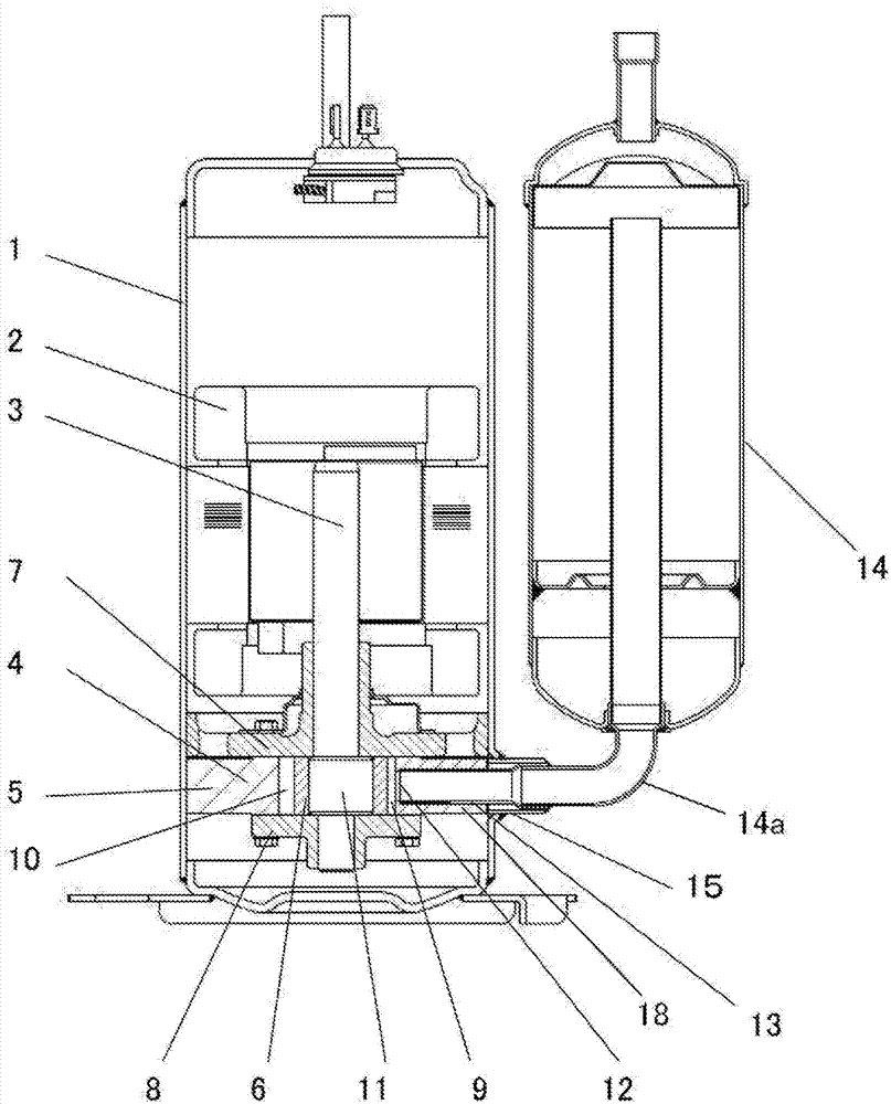
[0069] figure 1 It is a longitudinal sectional view of the compressor according to Embodiment 1 of the present invention.

[0070] figure 1 Among them, the electric component 2 and the compression mechanism part 4 are accommodated in the airtight container 1 . The electric component 2 and the compression mechanism unit 4 are connected by a drive shaft 3 . The compression mechanism unit 4 forms a suction chamber 9 and a compression chamber 10 by partitioning the space formed by the cylinder 5 and the rotary piston 6 between the upper bearing 7 and the lower bearing 8 with vanes (not shown). A crankshaft eccentric portion 11 integrally formed with the drive shaft 3 is accommodated in the cylinder 5 , and the rotary piston 6 is rotatably attached to the crankshaft eccentric portion 11 . A vane (not shown) is slidably provided on the cylinder 5 . The vane always abuts against the rotary piston 6 , thereby partitioning the suction chamber 9 and the compression chamber 10 . A...

Embodiment approach 2

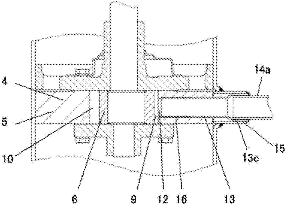
[0106] Figure 9 It is an enlarged sectional view of the vicinity of the suction hole of the compressor according to Embodiment 2 of the present invention. However, other configurations that are not shown are the same as those in Embodiment 1, and thus description thereof will be omitted.

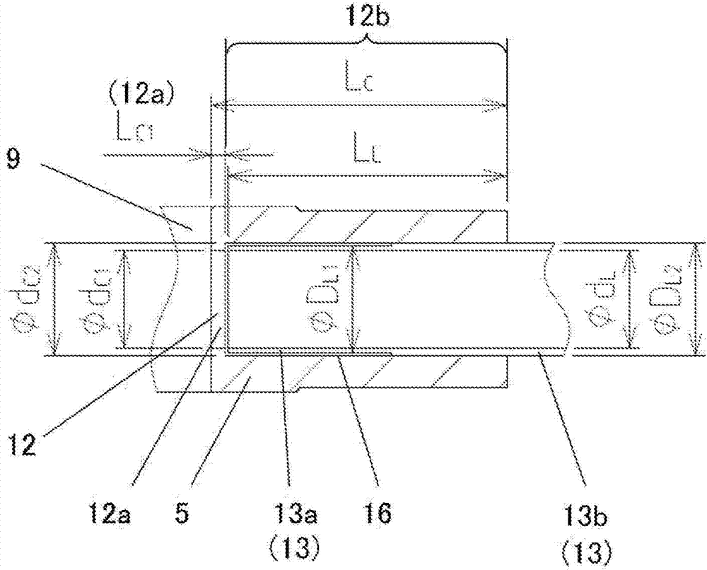
[0107] Figure 9 Among them, the step difference between the diameter-reduced portion 12a of the suction hole 12 and the diameter-enlarged portion 12b on the upstream side is a tapered shape at an angle α. The angle α is formed by machining the enlarged diameter portion 12b of the suction hole 12 with a drill. In the case of conventional drills, the angle α is 118 degrees.

[0108] With this configuration, the same effect as that of Embodiment 1 can be obtained, of course, but in addition, since the diameter-enlarged portion 12b of the suction hole 12 can be drilled, it can contribute to improvement of workability such as shortening of work time.

[0109] Figure 10 It is an enlarged c...

Embodiment approach 3

[0112] Figure 11 It is an enlarged sectional view of the vicinity of the suction hole of the compressor according to Embodiment 3 of the present invention. However, other configurations that are not shown are the same as those in Embodiment 1, and thus description thereof will be omitted.

[0113] like Figure 11 As shown, the outer diameter ΦD of the large diameter portion 13b of the suction liner pipe 13 L2 Set to be slightly smaller than the inner diameter Φd of the enlarged diameter portion 12b of the suction hole 12 C2 , and the high pressure and low pressure are separated by the O-ring 17 inserted into the upstream side of the suction hole 12 . In this embodiment, the O-ring 17 constitutes a partition.

[0114] According to this structure, since the high-temperature cylinder 5 and the suction liner pipe 13 are not in direct contact, the heating of the low-temperature and low-pressure suction refrigerant gas flowing through the suction liner pipe 13 can be further supp...


PUM


Abstract

A highly efficient compressor is provided in which an intake hole (12) has a reduced-diameter part (12a) located on the downstream side, and an enlarged-diameter part (12b) located on the upstream side, the non-contacting length from the downstream distal-end part of an intake liner (13) to the reduced-diameter part (12a) is less than the length of the reduced-diameter part (12a), a heat-insulating space (16) is formed between the intake liner (13) and the enlarged-diameter part (12b), the inside diameter [phi]d<C1> of the reduced-diameter part (12a) is the same as the inside diameter [phi]d<L> of the intake liner (13), and pressure loss can be kept to a minimum while movement of heat into intake refrigerant gas is suppressed in an intake duct path through which the intake refrigerant gas is led to an intake chamber.

Description

technical field [0001] The present invention relates to compressors used in air conditioners, refrigerators, blowers, water heaters, and the like. Background technique [0002] As an example of the structure of the prior art, refer to Figure 15 Be explained. Figure 15 It is a vertical cross-sectional view of a rotary high-pressure hermetic compressor. [0003] A suction chamber 105 and a compression chamber 118 are formed by dividing a space formed by sandwiching the cylinder 101 and the rotary piston 102 between the upper bearing 103 and the lower bearing 104 by vanes (not shown). Compression mechanism unit 107 and electric component 108 are accommodated in airtight container 109 . The compression mechanism unit 107 performs a compression operation when the rotary piston 102 rotates with the rotation of the drive shaft 106 . The electric component 108 transmits the rotational force to the drive shaft 106 . [0004] A suction hole 110 opening to the suction chamber 105 ...

Claims


Application Information

Patent Timeline
Patent Type & Authority Applications(China)
IPC IPC(8): F04C29/04F04C18/356F04C23/00F04C29/12
CPCF04C18/356F04C23/008F04C29/04F04C29/12F04C2240/806
Inventor 吉田裕文苅野健船越大辅鶸田晃中井启晶大野龙一饭田登大八木信吾
Owner PANASONIC CORP
Why Eureka
Try Eureka