Heat ray shielding material

A technology of heat ray shielding and metal particles, applied in the direction of thin material processing, instruments, coatings, etc., to achieve the effect of good visible light transmission

Inactive Publication Date: 2014-05-07
FUJIFILM CORP
View PDF9 Cites 2 Cited by
  • Summary
  • Abstract
  • Description
  • Claims
  • Application Information

AI Technical Summary

Problems solved by technology

However, Patent Document 3 has no description concerning particle segregation

Method used


Image

  • Heat ray shielding material
  • Heat ray shielding material
  • Heat ray shielding material

Examples


Embodiment

[0190] Features of the present invention will be described more specifically with reference to Examples given below.

[0191] In the following examples, materials used, their amounts and ratios, processing details, and processing procedures can be appropriately modified or changed without exceeding the scope of the present invention. Therefore, the scope of the present invention should not be limitedly interpreted by the Examples mentioned below.

manufacture example 1

[0192] (Manufacturing Example 1: Preparation of silver plate particle dispersion B1)

[0193] -Synthesis of silver plate particles (preparation of silver plate particle dispersion A)-

[0194] --Synthesis steps of flat core particles-

[0195] 2.5 ml of a 0.5 g / l polystyrene sulfonic acid aqueous solution was added to 50 ml of a 2.5 mM sodium citrate aqueous solution, and heated to 35°C. 3 ml of a 10 mM aqueous solution of sodium borohydride was added to the above solution, and 50 mL of a 0.5 mM aqueous solution of silver nitrate was added thereto at a rate of 20 mL / minute under stirring. The resulting solution was stirred for 30 minutes to prepare a seed solution.

[0196] --FIRST GROWTH STEP OF PLATE PELLETS-

[0197] Next, 2 mL of an aqueous 10 mM ascorbic acid solution was added to 250 mL of the seed solution and heated to 35°C. Under stirring, 79.6 mL of 0.5 mM silver nitrate aqueous solution was added to this solution at a rate of 10 mL / minute.

[0198] --Second Gro...

Embodiment 1

[0217] -Preparation of Coating Solution 1-

[0218] Coating liquid 1 having the composition shown below was prepared.

[0219] Composition of Coating Solution 1:

[0220]

[0221]

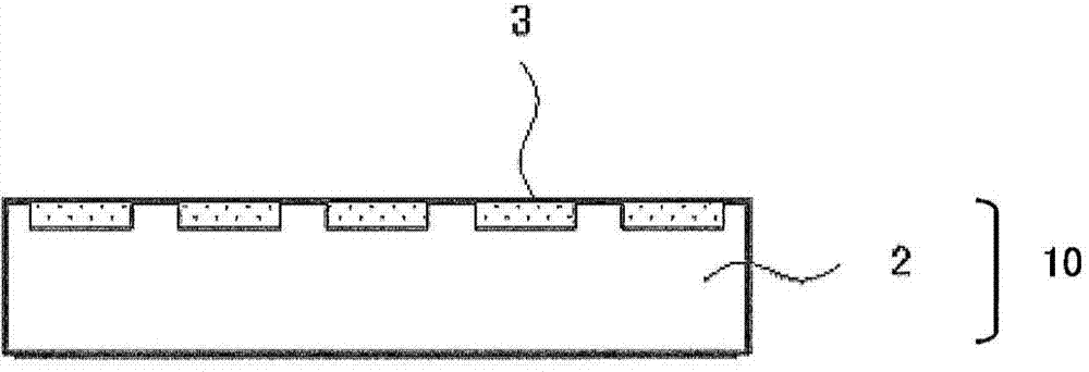
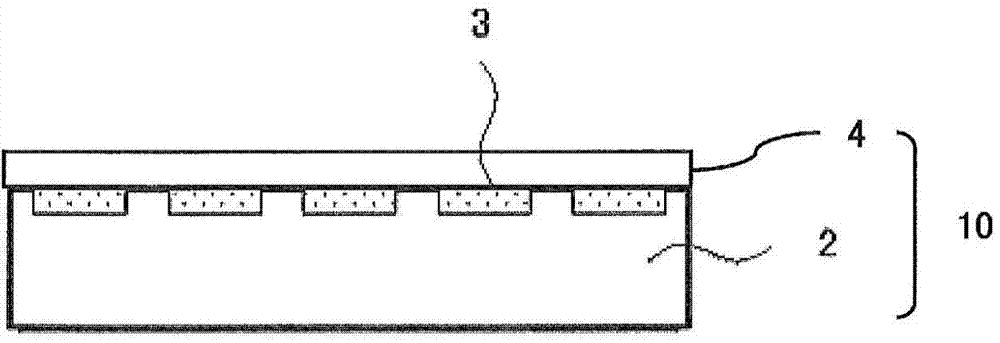
[0222] -Formation of Metal Particle Containing Layer-

[0223] Coating liquid 1 was applied onto the surface of a PET film (Cosmoshine A4300, Toyobo, thickness 75 μm) using a wire-wound bar so that the average thickness after drying could be 0.08 μm (80 nm). Subsequently, it was heated at 150° C. for 10 minutes, dried, and cured to form a metal particle-containing layer, whereby the heat ray shielding material of Example 1 was produced.

[0224] The average thickness of the metal particle-containing layer after drying was determined as follows: Using a laser microscope (VK-8510, Keyence), the thickness of the PET film that was not coated with the coating solution 1 was measured and the thickness of the PET film was measured after coating the coating solution 1, heating, The thickness of th...


PUM

PropertyMeasurementUnit
particle sizeaaaaaaaaaa
thicknessaaaaaaaaaa

Abstract

Favorable visible light transmittance, shielding performance (solar reflectance), and rubbing resistance are demonstrated by a heat ray shielding material having a metal particle-containing layer containing at least one type of metal particle, 60% or more of the metal particles being hexagonal or circular tabular metal particles. A principle plane of the hexagonal or circular plate-shaped metal particles is oriented at 0 DEG - + / -30 DEG on average with respect to one surface of the metal particle-containing layer. 80% or more of hexagonal or circular tabular metal particles are present within a range d / 2 from the surface of the metal particle-containing layer, where d is the thickness of the metal particle-containing layer.

Description

technical field [0001] The present invention relates to a heat ray shielding material having good visible light transmittance, heat shielding properties and friction resistance. Background technique [0002] In recent years, as an energy-saving measure for reducing carbon dioxide, materials imparting heat ray shielding properties have been developed for windows of vehicles and buildings. From the viewpoint of heat ray shielding (solar radiation heat gain rate), heat reflection type without re-radiation is required instead of indoor re-radiation of absorbed light (approximately 1 / 3 of absorbed solar energy) Heat absorption type, for which various schemes have been proposed. [0003] As an infrared shielding filter, a filter using Ag flat plate particles has been proposed (see Patent Document 1). However, since the infrared shielding filter film described in Patent Document 1 is intended to be used in a plasma display panel (PDP), and since the composition control of such Ag...

Claims


Application Information

Patent Timeline
Patent Type & Authority Applications(China)
IPC IPC(8): G02B5/26B32B7/02C03C17/32C03C17/36
CPCC03C17/007C03C17/366C03C2217/445C03C2217/465C03C2217/479G02B5/206G02B5/208Y10T428/256
Inventor 清都尚治泽登修
Owner FUJIFILM CORP
Why Eureka
Try Eureka