
Machine tool working condition real-time monitoring system based on wireless sensor network

A wireless sensor, real-time monitoring technology, used in manufacturing tools, metal processing equipment, metal processing mechanical parts, etc., can solve the problems of less data parameters, affecting the working stability of machine tools, motor life, and impact on machine tool production, etc., to achieve comprehensive monitoring. Effect

Inactive Publication Date: 2014-05-14
李宁 +12
View PDF0 Cites 25 Cited by
  • Summary
  • Abstract
  • Description
  • Claims
  • Application Information

AI Technical Summary

Problems solved by technology

[0002] Now in mechanized large-scale production, machine tools have become an indispensable part of production. Their operating parameters have a great impact on production efficiency and production safety. For example, the output torque of the spindle is an important functional index of machine tools. If its size is abnormal, it will affect the production of machine tools. It has a great influence; the tool is in direct contact with the workpiece, and it is prone to problems due to the large force during processing; the temperature of the motor affects the working stability of the machine tool and the life of the motor; security incident
[0003] Now there are real-time display of speed or output torque on the operation interface of advanced machine tools, but there are several disadvantages: 1. The data parameters displayed in the test are few, such as tool wear status, motor temperature, workpiece clamping status, etc. have not been measured; 2. .The displayed data is not accurate enough, and can only display the approximate range of torque or rotational speed; 3. The operators of large-scale factory production are limited, and it is impossible to know the working condition parameters of each machine tool in real time

Method used


Image

  • Machine tool working condition real-time monitoring system based on wireless sensor network
  • Machine tool working condition real-time monitoring system based on wireless sensor network
  • Machine tool working condition real-time monitoring system based on wireless sensor network

Examples


Embodiment Construction

[0028] The present invention will be further described below in conjunction with the accompanying drawings and examples.

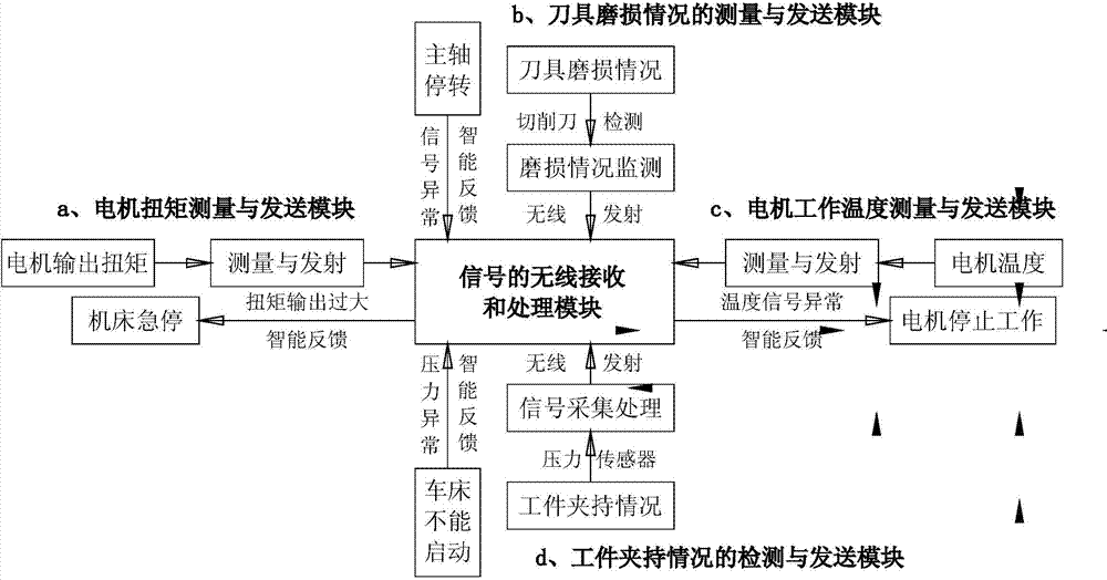
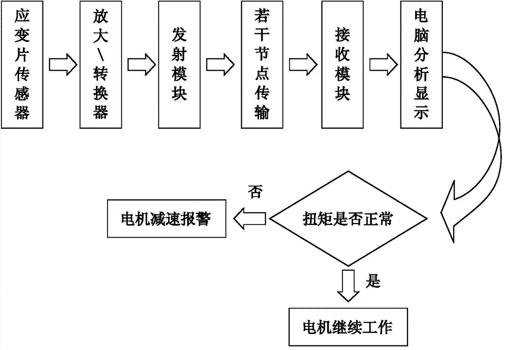
[0029] exist figure 1 , figure 2 , image 3 In the first embodiment shown, the measurement of the machine tool motor torque is carried out with the strain-type wireless torque sensor as the core component, and its main structure is to add a wireless transmission module on the basis of the dynamic torque sensor. The resulting strain-type wireless torque sensor is small in size and simple in structure, has the same characteristics as a dynamic torque sensor, and can convert the collected non-electricity signal into an electric quantity signal, and then transmit the signal wirelessly to the network node through single-chip processing and control place. The torque signal is transmitted between the nodes, and finally reaches the host computer terminal. The upper computer will use relevant software to reflect the signal in the form of a graph, so that the s...


PUM


Abstract

The invention relates to a machine tool working condition real-time monitoring system based on a wireless sensor network. The torque, the temperature of a motor, the cutter loss condition, the workpiece clamping condition and other parameters are measured through a torque sensor, a temperature sensor and other corresponding sensors installed on a machine tool. Data are sent in a wireless and multi-hop routing mode, and after receiving a signal, a single chip microcomputer processes the signal in a simple mode. The single chip microcomputer sends the data to an upper computer, final processing and displaying are carried out through software, and if data are abnormal, an alarm is given in real time, intelligent feedback is achieved, and related actions are carried out for processing. All machine tools in a factory are merged into the network, the networking real-time monitoring of production machines of the factory is achieved, and the monitoring cover degree and real-time performance are greatly improved.

Description

technical field [0001] The invention relates to a real-time monitoring system for working conditions of machine tools based on a wireless sensor network. Background technique [0002] Now in mechanized large-scale production, machine tools have become an indispensable part of production. Their operating parameters have a great impact on production efficiency and production safety. For example, the output torque of the spindle is an important functional index of machine tools. If its size is abnormal, it will affect the production of machine tools. It has a great influence; the tool is in direct contact with the workpiece, and it is prone to problems due to the large force during processing; the temperature of the motor affects the working stability of the machine tool and the life of the motor; security incident. [0003] Now there are real-time display of speed or output torque on the operation interface of advanced machine tools, but there are several disadvantages: 1. Th...

Claims


Application Information

Patent Timeline
IPC IPC(8): B23Q17/09B23Q17/00
CPCB23Q17/00B23Q17/007B23Q17/0952B23Q17/0957B23Q17/0961B23Q17/0985
Inventor 李宁宋剑峰欧科君徐汉斌吴鹏雷康吴坤王梓杭马小丹李杰何丽娜王一新刘念强
Owner 李宁
Learn More