Combination machining tool for installation position of door pocket frame

A technology of installation position and combined processing, which is applied in the direction of wood processing equipment and manufacturing tools, can solve the problems that the paired pieces cannot be matched well, the waste rate in the processing process is high, and the workload of production management is large, so as to reduce management. The effect of reducing workload, improving production efficiency and shortening processing cycle

Active Publication Date: 2014-05-14
NANTONG YUETONG CNC EQUIP CO LTD
View PDF7 Cites 32 Cited by
  • Summary
  • Abstract
  • Description
  • Claims
  • Application Information

AI Technical Summary

Problems solved by technology

[0003] The existing processing of the installation position of the frame of the door cover is carried out in steps. The fixed-length cutting, the processing of the top decorative plate groove, the processing of the hinge installation groove, and the processing of the bolt plate installation groove are completed on different machine tools. The processing cycle is long, the production efficiency is low, and the processing scrap rate is high.
In addition, the existing frame processing of the door cover is always processed one by one separately. Since the frame of the door cover is one piece on the left and right, the processing procedure and the shape of the installation groove are inconsistent, which makes the production management workload larger. , there is always a large processing error, so that the paired pieces cannot be matched well

Method used


Image

  • Combination machining tool for installation position of door pocket frame
  • Combination machining tool for installation position of door pocket frame
  • Combination machining tool for installation position of door pocket frame

Examples


Embodiment Construction

[0017] Refer to attached Figure 1-6 Shown, the structure of the present invention and its working process are described in more detail.

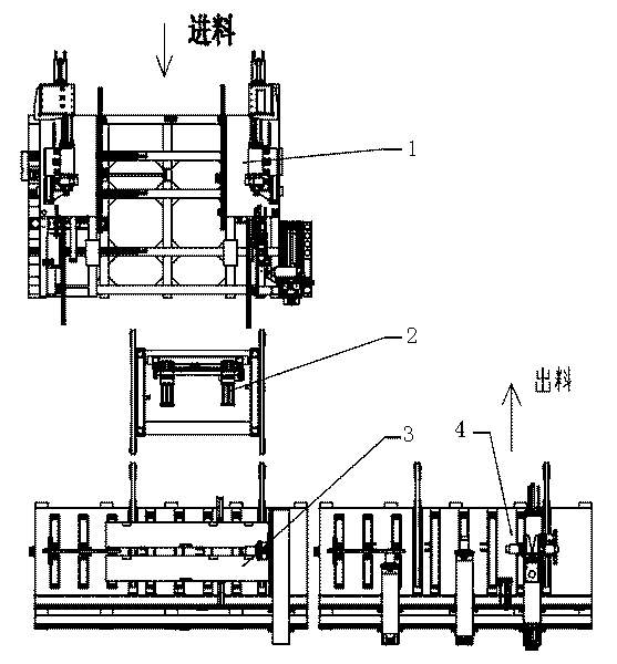
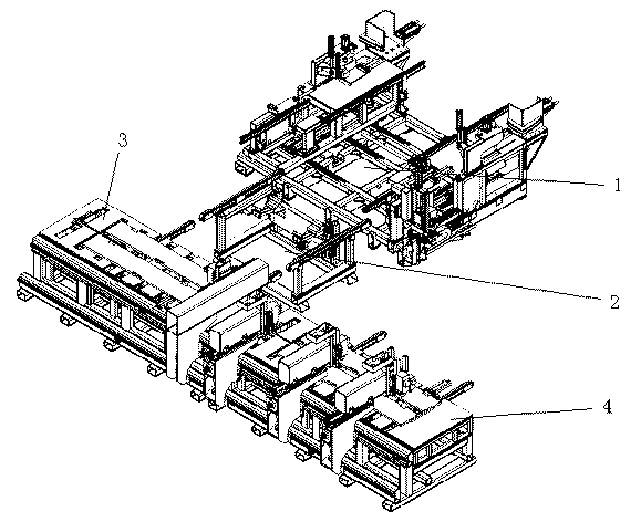
[0018] Such as figure 1 , 2 As shown, the combined processing machine tool for the installation position of the door frame frame includes a numerically controlled door frame sizing milling machine 1, a workpiece turning machine 2, a numerically controlled door frame drilling machine 3 and a numerically controlled door frame metal groove processing machine 4, each of which has Contained conveyor belts, the positional movement of the workpiece 5 on the combination machine tool is realized by these conveyor belts.

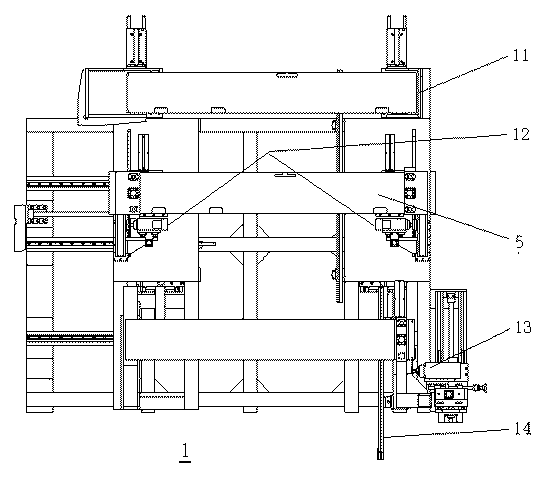
[0019] Such as image 3 As shown, the CNC door frame fixed-size slot milling machine 1 includes a bin 11 for storing the workpieces 5 to be processed. A cut-to-length station and a slot milling station, a pair of cutting devices 12 arranged on the back of the cut-to-length station, such as circular saws, are used to determine t...


PUM


Abstract

The invention relates to a combination machining tool for an installation position of a door pocket frame. The combination machining tool comprises a numerical control doorframe fixed-length slot milling machine 1, a workpiece turnover machine 2, a numerical control doorframe drilling machine 3 and a numerical control doorframe hardware slot machining machine 4. The numerical control doorframe fixed-length slot milling machine takes out a pair of workpieces 5 from the bottom of a stock bin 11 of the numerical control doorframe fixed-length slot milling machine every time for conducting fixed-length cutting and decoration plate slot milling, wherein the front faces of the workpieces 5 face each other, and the workpieces 5 are stacked vertically. Then, the pair of workpieces are conveyed to the workpiece turnover machine, the workpiece turnover machine turns over the upper workpiece so as to enable the front faces of the pair of workpieces to face upwards, then the workpieces are fed into the numerical control doorframe drilling machine together, after all holes are machined in the workpieces, the pair of workpieces are fed into the numerical control doorframe hardware slot machining machine for machining doorframe hinge slots and doorframe spring bolt slots in the workpieces at the same time, and after the slot machining is completed, the workpieces are conveyed out in pairs. The machining tool has the advantages of being high in efficiency and product consistency and low in rejection rate.

Description

technical field [0001] The patent application of the present invention relates to a woodworking processing machine, in particular to a machine tool for combining the installation position of a door cover frame. [0002] Background technique [0003] The existing processing of the installation position of the frame of the door cover is carried out in steps. The fixed-length cutting, the processing of the top decorative plate groove, the processing of the hinge installation groove, and the processing of the bolt plate installation groove are completed on different machine tools. The processing cycle is long, the production efficiency is low, and the scrap rate in the processing process is high. In addition, the existing frame processing of the door cover is always processed one by one separately. Since the frame of the door cover is one piece on the left and right, the processing procedure and the shape of the installation groove are inconsistent, which makes the production m...

Claims


Application Information

Patent Timeline
Patent Type & Authority Applications(China)
IPC IPC(8): B27M3/00B27M1/08
Inventor 张海建黄海涛范进冒旭东姚遥
Owner NANTONG YUETONG CNC EQUIP CO LTD
Why Eureka
Try Eureka