Ink pot device

A technology of ink pots and inks, applied in printing, printing machines, general parts of printing machinery, etc., can solve problems such as difficult cleaning and ink residue, and achieve the effect of improving reproducibility

Inactive Publication Date: 2014-05-14
JPE
View PDF7 Cites 0 Cited by
  • Summary
  • Abstract
  • Description
  • Claims
  • Application Information

AI Technical Summary

Problems solved by technology

[0013] In the device for preventing ink leakage described in Patent Document 2, the magnet sheet placed on the ink squeegee has flexibility, no permanent deformation, improved adhesion, and ink intrusion can be prevented. The magnetic force on the top of the inkpot body needs to be thickened, and there is a step difference between the front end, left and right ends of the magnet piece and the top of the inkpot body, and a large amount of ink remains on the step difference, which is difficult to clean.
[0014] In the device for preventing ink leakage described in Patent Document 3, the cleaning of the upper second cover in contact with the ink is simple and convenient, but in order to clean the first cover, if it slides in the direction away from the main ink roller, it will remain on the first cover. The ink at the end of the cap may be drawn between the ink scrapers, and there is a problem that a large amount of ink remains on the step between the front end and the left and right ends of the thick cap, making it difficult to clean.

Method used


Image

  • Ink pot device
  • Ink pot device
  • Ink pot device

Examples


Embodiment Construction

[0065] Hereinafter, embodiments of the inkpot device according to the present invention will be described in detail with reference to the accompanying drawings. In the following embodiments, although various limitations are made to constituent elements, types, combinations, shapes, relative arrangements, etc., these are merely examples. For example, the present invention is not limited thereto.

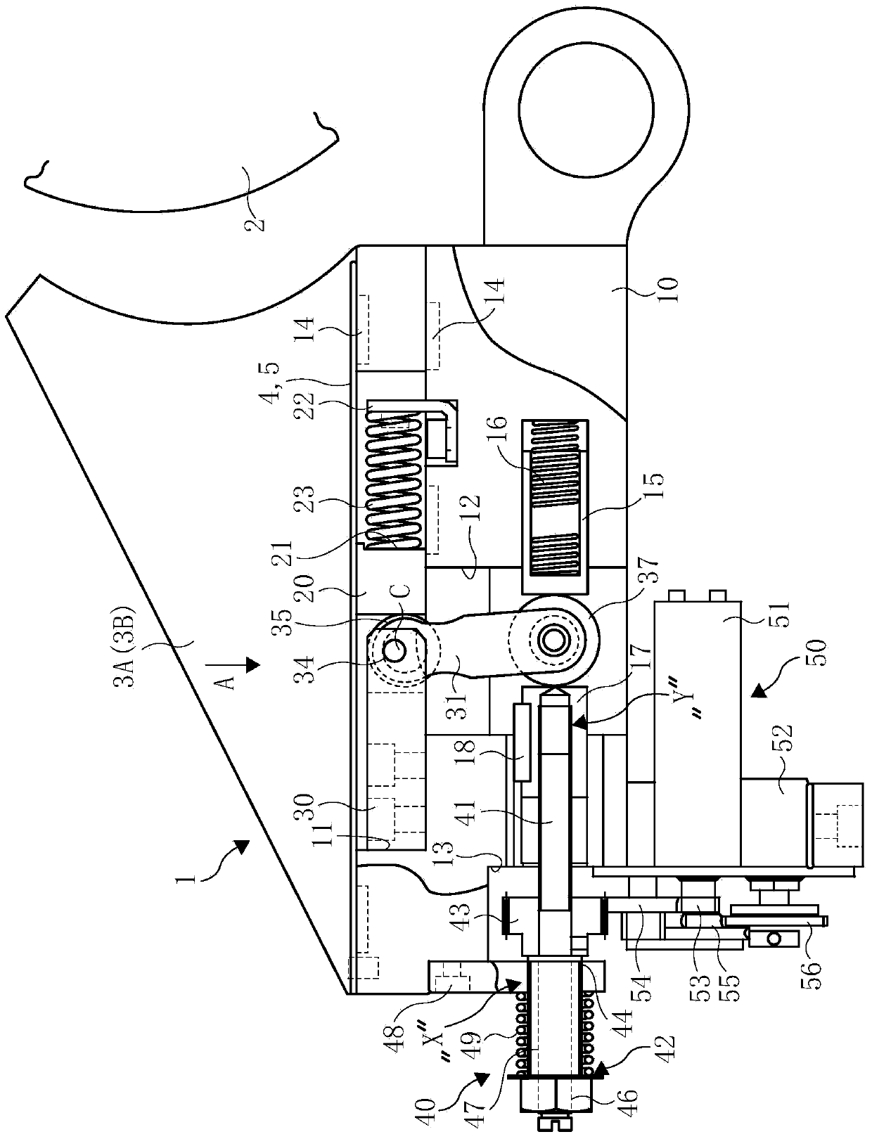
[0066] figure 1 The shown ink pot device 1 is composed of an ink main roller 2 pivotally supported on the frame of a printing machine not shown in the figure, a rectangular parallelepiped ink pot body 10 having approximately the same length as the ink main roller 2, and disposed on the main body 10. The ink baffles 3A and 3B on the two sides above and the two cover plates 4 and 5 covering the body 10 are composed of the main ink roller 2 as the front, the cover plate 5 as the bottom surface, and the ink baffles 3A and 3B as the bottom surface. The two sides are surrounded to form a ...


PUM


Abstract

The invention relates to an ink pot device which comprises an ink main roller, an ink baffle, an ink pot body, a connecting rod, a connecting rod support and an ink scraping plate. A step difference portion is formed on the upper portion of the ink pot body, the connecting rod swings in the ink pot body through driving force and is provided with an eccentrically-moving eccentric wheel, the connecting rod support supports the connecting rod and is arranged on the step difference portion in a supported manner, the ink scraping plate is arranged on the step difference portion in a supported manner and usually connected with the eccentric wheel, and can move along the front-rear direction, an adjusting unit is arranged on the ink pot body in a matched manner, a push rod usually connected with a free end of the connecting rod and capable of advancing and retreating is screwed at the front end of the adjusting unit in a threaded manner, the adjusting unit is composed of a transmission shaft portion, an adjusting screw portion and a gear portion and used for fine adjusting of the ink scraping plate, the adjusting screw portion is in threaded connection with a bracket vertically arranged on the ink pot body, and is connected with a flange portion formed on the transmission shaft portion through an elastic part, and the gear portion is meshed with a gear of a driving unit and driven by a motor to rotate backwards. By the ink pot device, reproducibility of zero point adjusting can be improved, adjusting difficulty can be lowered, and ink leakage can be prevented.

Description

[0001] This application is a divisional application of the Chinese invention patent application with the application number 201010293358.X, the application date is September 26, 2010, the applicant is JPE Corporation, and the invention name is "ink pot device". technical field [0002] The present invention relates to an inkpot device for a printing machine, and more particularly to an inkpot device that improves the reproducibility of zero point adjustment for adjusting the zero point associated with the movement of a squeegee that has been a long-standing problem, and improves the prevention of ink leakage. Background technique [0003] In the ink pot device that supplies ink to the plate cylinder of the printing press, the ink pot that stores the ink is adjacent to the ink main roller that rotates and sends ink at a low speed, and a plurality of ink scrapers are provided so that the rotation of the ink main roller The sent ink becomes the ink film thickness of the necessar...

Claims


Application Information

Patent Timeline
Patent Type & Authority Applications(China)
IPC IPC(8): B41F31/04
Inventor 熊木恒夫桥本邦彦
Owner JPE
Why Eureka
Try Eureka