
Cloth gripping device

A grabbing device and cloth technology, applied in the direction of textiles and papermaking, sewing equipment, sewing machine components, etc., can solve the problems of small range, waste of energy, energy consumption, etc., achieve the effect of wide cloth range, reduce air leakage, and save energy

Active Publication Date: 2014-05-14
JACK SEWING MASCH CO LTD
View PDF6 Cites 21 Cited by
  • Summary
  • Abstract
  • Description
  • Claims
  • Application Information

AI Technical Summary

Problems solved by technology

[0003] The sewing machine used now has gradually changed from the previous manual to automatic, and the cloth can also be automatically supplied by some machinery. When the sewing machine is working, the supply or grabbing of the cloth is mostly completed by a cloth suction device with a suction cup-shaped suction head. The suction device uses vacuum force to absorb the cloth and move it to the predetermined position, but there are still some shortcomings in the use of this device: (1) The applicable cloth range is small, and it can only be used for the cloth with very dense yarn fibers. , and most of the fabrics are knitted or woven, the gaps between the yarn fibers of these fabrics are relatively large, and there will be air leakage during the actual suction device, causing the fabric to not be absorbed; (2) due to the yarn of the fabric There is a gap between the fibers, the cloth and the suction cup, so the suction head needs to consume a lot of power to achieve the required vacuum degree, thus wasting energy; The distribution is different. In many cases, the binding force between the suction cup and the uppermost layer of cloth is smaller than that between the cloth layers. This makes it impossible to ensure that only the uppermost cloth is sucked every time when absorbing, but often occurs simultaneously. In the case of absorbing multiple pieces or not even one piece, the automatic control with poor reliability of this kind of action is very unsatisfactory; (4) Since there is no grasping structure between the ordinary suction cup and the yarn fibers of the cloth, it is difficult to separate and In the process of moving the fabric, it is necessary to maintain a strong vacuum to maintain a certain suction force, so it consumes more energy and is accompanied by a lot of noise during work

Method used

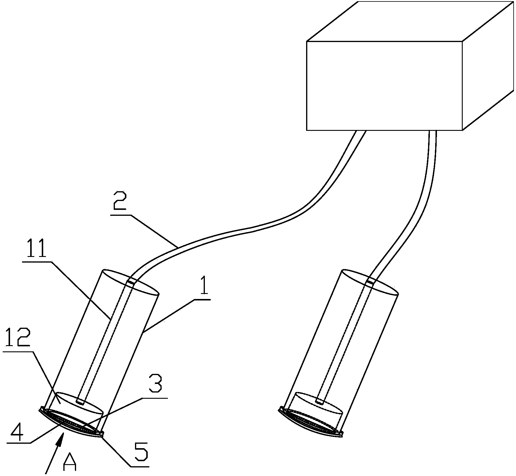
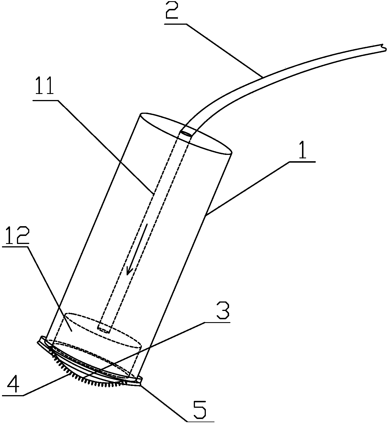

Image

  • Cloth gripping device
  • Cloth gripping device
  • Cloth gripping device

Examples


Embodiment Construction

[0031] The structures, proportions, sizes, etc. shown in the accompanying drawings of the description are only used to match the content disclosed in the description, for those who are familiar with the technology to understand and read, and are not used to limit the conditions for the implementation of the present invention, so there is no Technically, any modification of structure, change of proportional relationship or adjustment of size shall still fall within the scope of the technical content disclosed in the present invention without affecting the functions and objectives of the present invention. within the range that can be covered. At the same time, terms such as "upper", "lower", "front", "rear", and "middle" quoted in this specification are only for the convenience of description, and are not used to limit the scope of the present invention. , the change or adjustment of its relative relationship, without substantive changes in the technical content, should also be...


PUM


Abstract

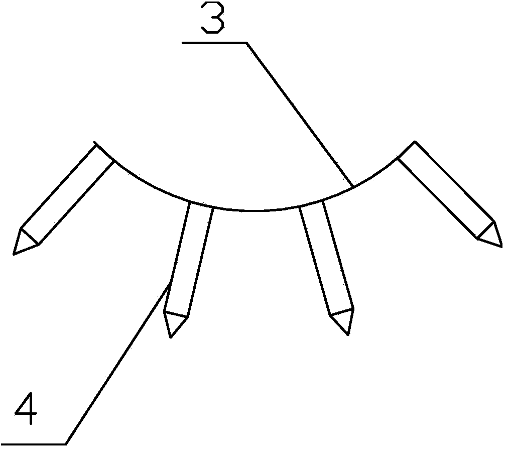
The invention provides a cloth gripping device which comprises a gripping arm body. One end of the gripping arm body is provided with a cavity. One end of the cavity is covered with an elastic film piece arranged on the gripping arm body. The elastic film piece is provided with a through hole. The other end of the cavity is connected with an air pipe. The outer side of the elastic film piece is provided with a plurality of rows of needle-shaped protrusions. According to the cloth gripping device, by means of the adsorption force of air pressure and the clamping force of the needle-shaped protrusions, automatic feeding of cloth is stable and reliable. Moreover, due to the clamping function of the needle-shaped protrusions, the applicable cloth range of the cloth gripping device is wide. In addition, due to the special structure, the energy consumption in the working process of the cloth gripping device is small and the noise is low.

Description

technical field [0001] The invention relates to an auxiliary device of a sewing machine, in particular to a cloth grabbing device. Background technique [0002] With the development of the sewing machine industry, more and more sewing machines are used in different fields of production and life, and the auxiliary equipment matched with the sewing machine is gradually enriched. [0003] The sewing machine used now has gradually changed from the previous manual to automatic, and the cloth can also be automatically supplied by some machinery. When the sewing machine is working, the supply or grabbing of the cloth is mostly completed by a cloth suction device with a suction cup-shaped suction head. The suction device uses vacuum force to absorb the cloth and move it to the predetermined position, but there are still some shortcomings in the use of this device: (1) The applicable cloth range is small, and it can only be used for the cloth with very dense yarn fibers. , and most ...

Claims


Application Information

Patent Timeline
IPC IPC(8): D05B33/00
Inventor 钱坤蔡姚杰陈志强赵子恺
Owner JACK SEWING MASCH CO LTD
Learn More