Casing pipe bending moment compensator special for thermal recovery horizontal well

A technology of horizontal wells and compensators, which is applied in the direction of casing, drilling pipe, and production fluid, etc., can solve the problems of stress concentration, failure to provide bending moment compensation, downhole sand production, etc., and achieve strong applicability, significant economic benefits, Effects requiring low usage conditions

Inactive Publication Date: 2014-05-14
CHINA PETROLEUM & CHEM CORP +1
View PDF8 Cites 4 Cited by
  • Summary
  • Abstract
  • Description
  • Claims
  • Application Information

AI Technical Summary

Problems solved by technology

Today's scholars have already confirmed that the corrosion rate of the pipe string in the stress concentration area is dozens of times that of the non-stress concentration area. Therefore, if the stress concentration area is not effectively compensated, it is very easy to be damaged and cause downhole sand production.
At present, all compensators, no matter the shear nail type with application number 201020213151.2, or the hot-melt type with application number 200910017792.2, can only compensate in the axial direction of the pipe string, and the bending moment generated by the horizontal section of the horizontal well Stress concentration is powerless to provide bending moment compensation

Method used


Image

  • Casing pipe bending moment compensator special for thermal recovery horizontal well

Examples


Embodiment Construction

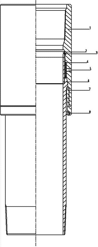
[0007] The present invention is described in detail below in conjunction with accompanying drawing, see figure 1 , the special casing bending moment compensator for thermal recovery horizontal wells includes an outer cylinder 1, a hot-melt limit ring 4 and a lower inner cylinder 6, connecting the upper inner cylinder 2 with the lower inner cylinder 6, together with the heat-melt limit ring 4 After being put into the outer cylinder 1 together, the stop ring 7 is used to connect the outer cylinder 1 with threads; , Concave spherical mating surface. The pipe string formed by the upper inner cylinder 2 and the lower inner cylinder 6 can take the spherical mating surface as the axis and bend arbitrarily in all directions within a preset angle to adapt to the actual wellbore changes of the oil zone. Both ends of the outer cylinder 1 are provided with inner threaded buckles, and the inner circle is sequentially processed from top to bottom to protect the inner cylinder with steps, s...


PUM


Abstract

The invention relates to a casing pipe bending moment compensator special for a thermal recovery horizontal well. The casing pipe bending moment compensator special for the thermal recovery horizontal well is connected with a steam injection section of a cased hole completion pipe pillar and can meet the requirements for a steam injection process of a recovery well casing pipe pillar. The casing pipe bending moment compensator special for the thermal recovery horizontal well comprises an outer barrel, a hot-melt limiting ring and a lower inner barrel, wherein an upper inner barrel is connected with the lower inner barrel, the upper inner barrel and the hot-melt limiting ring are put in the outer barrel together and then connected with the outer barrel through a blocking ring in a thread bucking mode, the outer circle of the upper portion of the upper inner barrel is a conical surface, and the outer circle of the upper portion of the lower inner barrel and the inner circle of the middle of the outer barrel are convex and concave spherical matching surfaces. When the hot-melt limiting ring is melted by the high temperature of injected steam, a pipe string formed by the upper inner barrel and the lower inner barrel can be bent to adapt to the actual variation of a well body of an oil layer section, the unfavorable situation that in the prior art the bending moment of the casing pipe pillar can not be compensated, and the safety of the cased hole completion pipe pillar is improved. The casing pipe bending moment compensator special for the thermal recovery horizontal well is simple in structure, reliable in work and complete in function, keeps the inner drift diameter of the casing pipe unchanged after the bending moment of the casing pipe is compensated, is low in cost and is high in adaptability.

Description

technical field [0001] The invention relates to a thermal stress compensation tool required for casing pipe strings of heavy oil thermal recovery wells in the petroleum industry, in particular to a special casing bending moment compensator for thermal recovery horizontal wells, which is connected in the steam injection section of the casing completion pipe strings, It can meet the requirements of thermal recovery well casing string for steam injection process. Background technique [0002] Due to the large-scale promotion of horizontal well technology in oil fields, some problems that were not considered at the beginning have also emerged. For example, the thermal stress problem of thermal recovery horizontal wells has become increasingly prominent, which is limited by the current actual drilling technology and the complexity of the actual downhole situation. The wellbore trajectory of horizontal wells often has some small bends. These bends generally lead to some difficulti...

Claims


Application Information

Patent Timeline
Patent Type & Authority Applications(China)
IPC IPC(8): E21B43/24E21B17/08
Inventor 朱瑛辉张全胜王世杰田玉刚伊伟锴杨慧温盛魁岳广韬张化强李冬梅
Owner CHINA PETROLEUM & CHEM CORP
Why Eureka
Try Eureka