
Oil pan component with high-flexibility oil baffle

A technology of oil baffle and oil pan, which is applied in the direction of engine components, engine lubrication, machine/engine, etc. It can solve the problems of adding extra load, cracking of oil pan welds, weakening of oil pan strength, etc., to achieve Reduce the tensile stress, reduce the force transmitted to the weld by oil impact, and improve reliability

Inactive Publication Date: 2014-05-14
GUANGXI YUCHAI MASCH CO LTD
View PDF6 Cites 4 Cited by
  • Summary
  • Abstract
  • Description
  • Claims
  • Application Information

AI Technical Summary

Problems solved by technology

[0004] After the oil baffle is welded to the oil pan, welding thermal stress and welding tensile stress will be generated, which will weaken the strength of the oil pan, and when the oil hits the oil baffle, it will add additional load to the weld of the oil pan, resulting in oil Cracks at the weld seam of the bottom shell

Method used


Image

  • Oil pan component with high-flexibility oil baffle
  • Oil pan component with high-flexibility oil baffle
  • Oil pan component with high-flexibility oil baffle

Examples


Embodiment Construction

[0017] The specific embodiments of the present invention will be described in detail below in conjunction with the accompanying drawings, but it should be understood that the protection scope of the present invention is not limited by the specific embodiments.

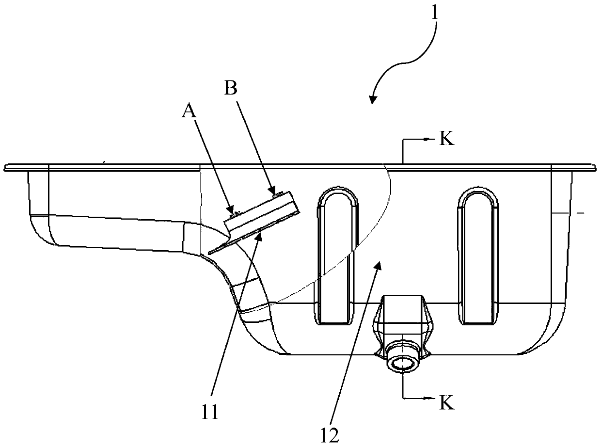
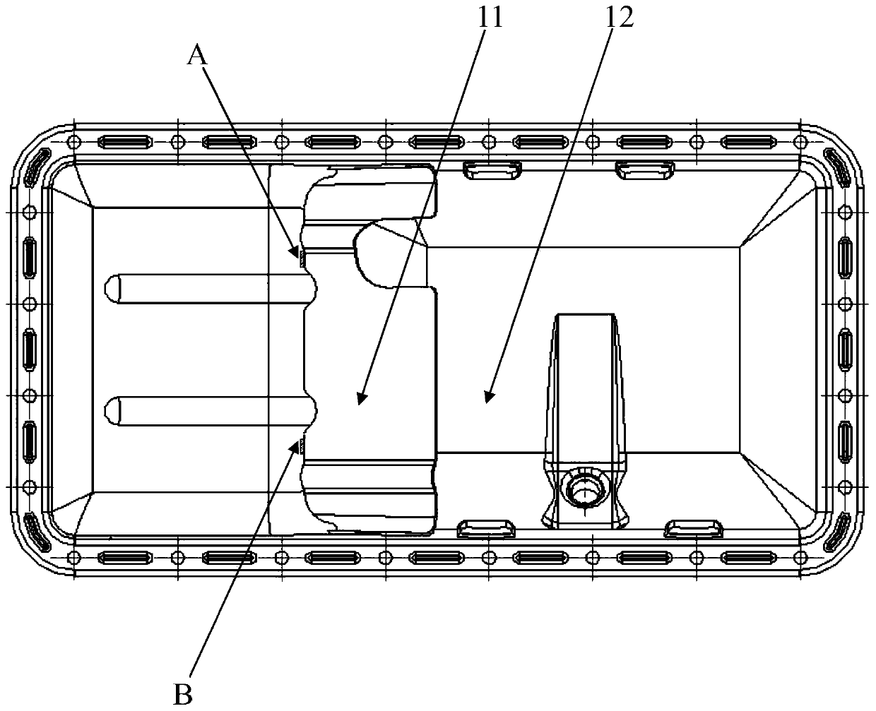
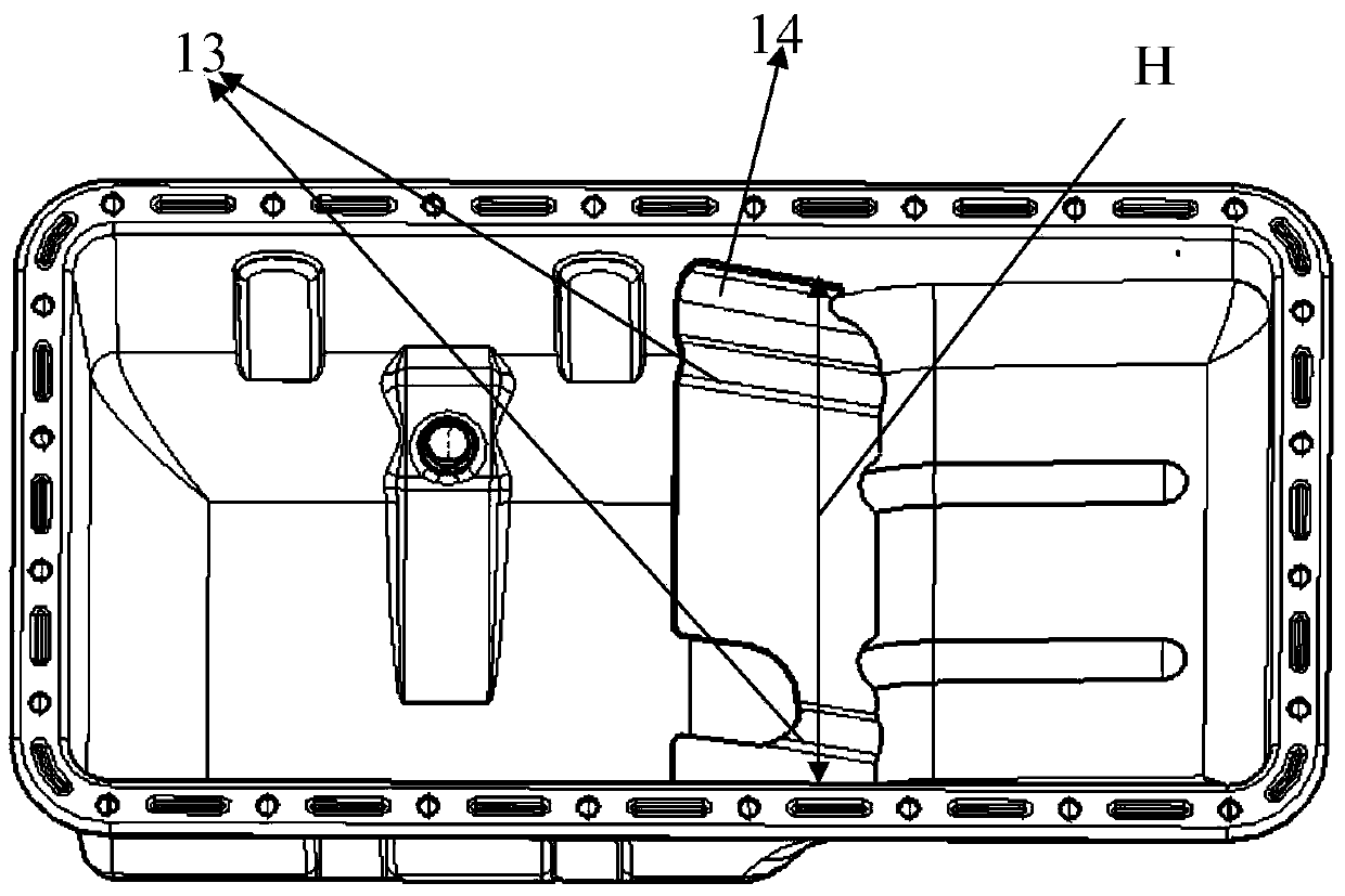
[0018] Such as Figure 1 to Figure 3 , which shows a schematic diagram of an oil pan assembly 1 according to a specific embodiment of the present invention.

[0019] Such as figure 1 and figure 2 As shown, the oil pan assembly 1 includes an oil baffle 11 and an oil pan body 12 . The oil baffle plate 11 is installed in the oil sump body 12 and connected with the oil sump body 12 by intermittent spot welding. in figure 1 and figure 2 A part of intermittent welding points A and B are shown in . It should be noted that the position of the welding points is only an example, and those skilled in the art can choose multiple Intermittent solder joints. Since the oil baffle plate 11 and the oil pan body 12 are connecte...


PUM


Abstract

The invention discloses an oil pan component with a high-flexibility oil baffle. The oil pan component comprises an oil pan body and the oil baffle, and the oil baffle is mounted in the oil pan body and in intermittent spot welding connection with the oil pan body and longitudinally provided with one or more buffering ribs. By means of spot welding connection of the oil baffle and the oil pan body, welding stress is reduced. Owing to the buffering ribs longitudinally arranged on the oil baffle, transverse flexibility of the oil baffle is improved, and tensile stress after welding is reduced.

Description

technical field [0001] The invention relates to the field of engine accessories, in particular to an engine oil pan assembly. Background technique [0002] The oil sump is located at the bottom of the engine, and its function is to close the crankcase as the casing of the oil storage tank, prevent impurities from entering, and collect and store the lubricating oil flowed back by the friction surfaces of the diesel engine. An oil baffle is installed inside the oil pan to avoid the shock and splash of the oil surface caused by the bumping of the diesel engine, and to facilitate the precipitation of lubricating oil impurities. [0003] In the prior art, for stamped oil pans, generally the oil baffle is directly welded to the oil pan. The oil baffle is provided with small rounded corners or no flanging. The lateral width of the oil baffle is smaller or the same as the width of the inner cavity of the oil pan for easy insertion into the oil pan. The oil baffle has no ribs or is ...

Claims


Application Information

Patent Timeline
Patent Type & Authority Applications(China)
IPC IPC(8): F01M11/00
Inventor 梁德浦王羽向本杰李湘华刘益军
Owner GUANGXI YUCHAI MASCH CO LTD
Learn More