
Pressure regulating valve

A pressure regulating valve and valve body technology, applied in the field of pressure regulating valves, can solve problems such as poor pressure regulation accuracy, narrow pressure regulation range, and large noise, and achieve the effect of low noise and high pressure regulation accuracy

Inactive Publication Date: 2014-05-14
BEIHANG UNIV
View PDF6 Cites 4 Cited by
  • Summary
  • Abstract
  • Description
  • Claims
  • Application Information

AI Technical Summary

Problems solved by technology

[0004] In the gas flow path of the regulating valve, the gas has two sections of 90° turning. This kind of structure itself makes this type of pressure regulating valve have the disadvantages of narrow pressure regulating range and small flow capacity.
In addition, because the butterfly valve adopts the principle of slit throttling and pressure regulation, on the one hand, the outlet gas pressure is greatly affected by the inlet gas pressure fluctuations, and the pressure regulation accuracy is poor; device

Method used


Image

  • Pressure regulating valve
  • Pressure regulating valve
  • Pressure regulating valve

Examples


Embodiment Construction

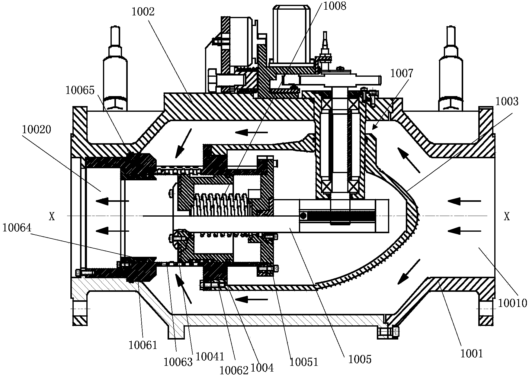
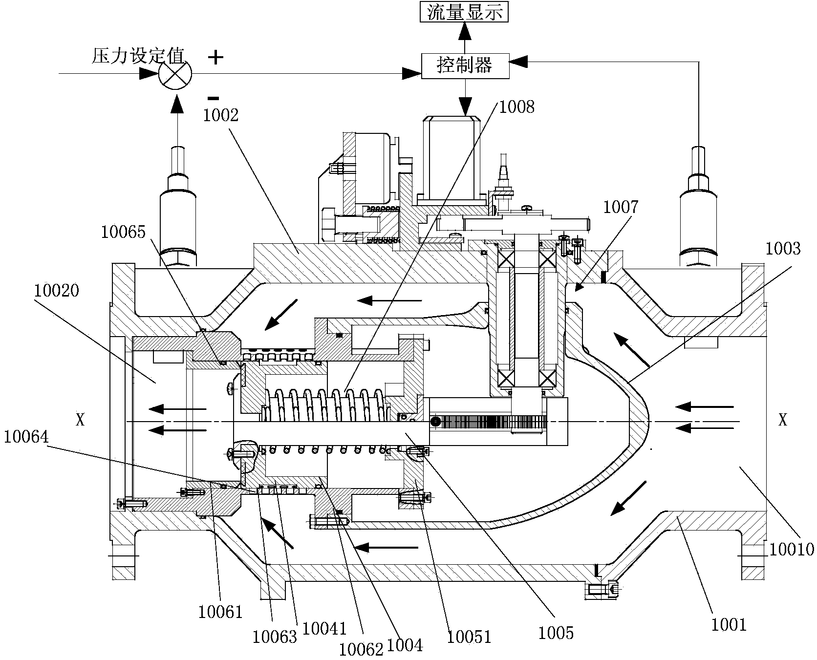
[0028] Specific embodiments of the present invention will be described in detail below in conjunction with the accompanying drawings. It should be understood that the embodiments described below are only illustrative and not restrictive.

[0029] [Overall structure of pressure regulator]

[0030] figure 1 and figure 2 Schematically shows the overall structure of a pressure regulating valve according to an embodiment of the present invention, wherein, figure 1 Shows the open state of the pressure regulating valve. In this state, the pressure regulating valve acts as a pressure regulator for adjusting the gas pressure flowing through the pressure regulating valve. figure 2 The closed state of the pressure regulating valve is shown. In this state, the pressure regulating valve is closed to cut off the gas flow path.

[0031] Such as figure 1 and figure 2 As shown, the pressure regulating valve includes: a valve body, which is composed of a right valve body 1001 and a ...


PUM


Abstract

The invention provides a pressure regulating valve. The pressure regulating valve comprises a valve body, a rectifier cover, a flow guide screen sleeve and a piston. The valve body is provided with an inlet and an outlet. The rectifier cover is arranged close to the inlet of the valve body and is suitable for guiding influent fluid in a mode of not interfering the fluid flowing into the valve body virtually. A through-flow part of the flow guide screen sleeve is provided with a plurality of through holes extending in the axial direction of the flow guide screen sleeve. The fluid flowing into the valve body from the inlet flows to the downstream side through the through holes and flows out of the valve body from the outlet. The piston can move in the axial direction of the flow guide screen sleeve so as to be jointed with the inner wall of the flow guide screen sleeve, the total area of the through holes through which the fluid flows in the flow guide screen sleeve is controlled by controlling the jointing position of the piston and the inner wall of the flow guide screen sleeve, and therefore the pressure regulating function is achieved. The pressure regulating valve can greatly improve flow and enable the pressure regulating range to be large, and is high in pressure regulating accuracy and low in noise.

Description

technical field [0001] The invention relates to a pressure regulating valve used in a gas supply system, in particular to an improvement of a gas flow path structure for a pressure regulating valve. Background technique [0002] In the gas supply system, the pressure regulating valve is used to adjust the pressure of the medium and high pressure pipeline network of pipeline gas to enter the low pressure user. For example, the pressure of pipeline gas pipelines is usually medium pressure (0.2-0.4MPa), high pressure (2.5-4MPa) or sub-high pressure (0.8-1.6Mpa). For the pressure regulating valve used in the pipeline gas pipeline network, it is expected that the pressure regulating valve has a large flow capacity and a wide pressure regulating range, so that the main gas transmission pipeline network can expand the gas supply range and reduce the number of urban pressure regulating stations. ,Improve economic efficiency. [0003] At present, most of the pressure regulating val...

Claims


Application Information

Patent Timeline
Patent Type & Authority Applications(China)
IPC IPC(8): F16K3/32F16K3/314
CPCF16K3/32F16K3/314F16K27/041F16K37/005
Inventor 刘永光杨晓伟高晓辉甘家建王一轩刘文磊程楠楠孙健
Owner BEIHANG UNIV
Learn More