Display device without frame

A display device, borderless technology, applied in nonlinear optics, instruments, optics, etc., can solve the problems of reliability, high positioning, and unreasonable connection structure of connectors

Inactive Publication Date: 2014-05-14
BEIJING BOE DISPLAY TECH CO LTD +1
View PDF5 Cites 17 Cited by
  • Summary
  • Abstract
  • Description
  • Claims
  • Application Information

AI Technical Summary

Problems solved by technology

However, the connection structure of the connector used in the borderless liquid crystal display device in the prior art has the following problems: the connection structure of the connector is unreasonable, which affects the overall strength of the liquid crystal display panel, and there are problems of reliability and L0 light leakage; and the connector The existence of the liquid crystal display device affects

Method used


Image

  • Display device without frame
  • Display device without frame
  • Display device without frame

Examples


Embodiment 1

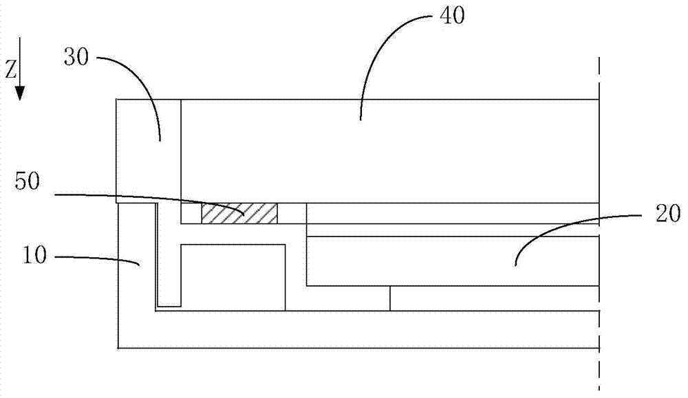
[0051] figure 2 Shown is a schematic diagram of a first embodiment of the present invention.

[0052] Such as figure 2 As shown, in this embodiment, the borderless display device includes a display panel 100, a panel connector 200 and a backlight, wherein the display panel 100 includes a display surface and a back surface opposite to the display surface, and the panel connector 200 One end of which is fixed on the peripheral area of ​​the back of the display panel 100, the other end of the panel connector 200 is formed with a first support surface 201 for supporting the display panel 100, and the first support surface 201 is formed with The first buckle part, the display panel 100 and the panel connector 200 together form a display panel 100 module;

[0053] The backlight module includes a back plate 300, a plastic frame 400 and an optical assembly 700, the back plate 300 and the plastic frame 400 are both arranged on the back side of the display panel 100, and the optical...

Embodiment 2

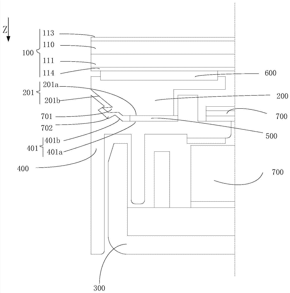
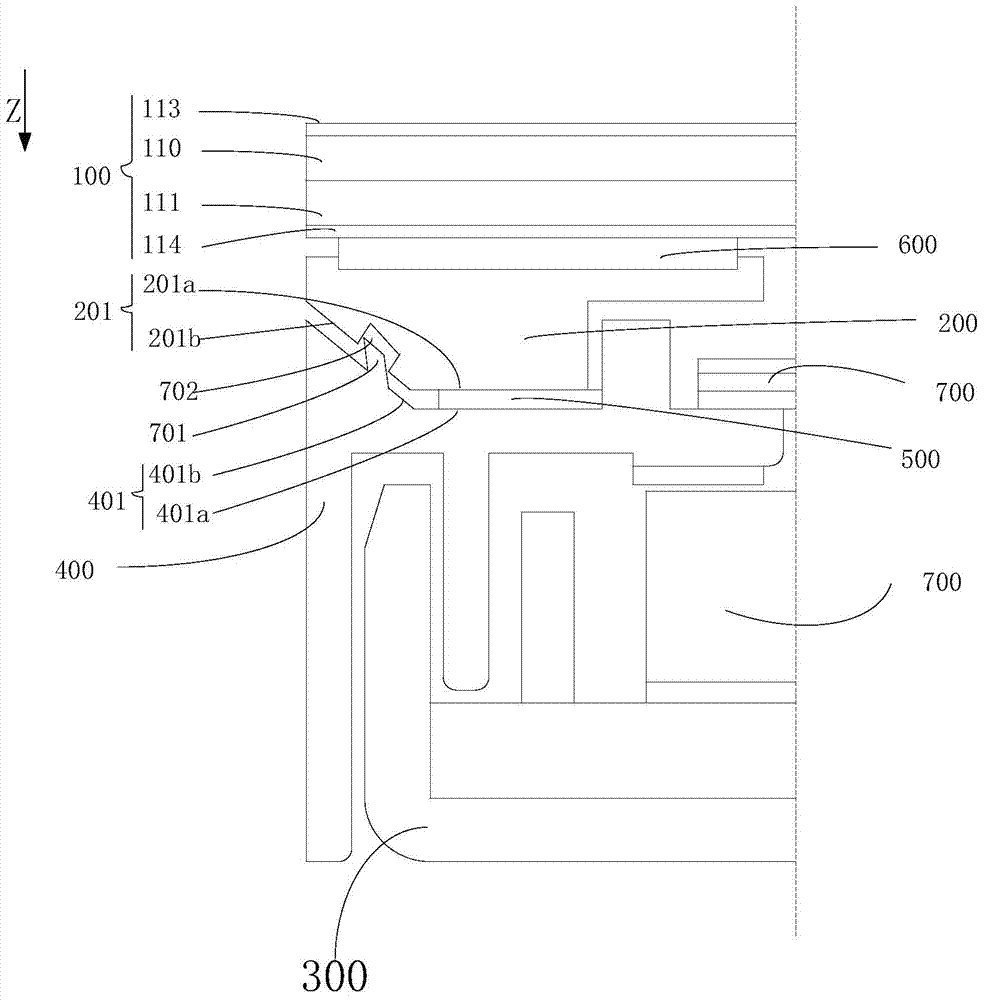
[0061] image 3 Shown is a schematic diagram of a second embodiment of the present invention.

[0062] Such as image 3 As shown, the present embodiment is the same as Embodiment 1 in that they both use the cooperation of the hook 701 and the hook groove 702 to realize the engagement and fixation of the panel connector 200 and the plastic frame 400, and both adopt the cooperation of an inclined plane to realize the engagement. Guiding and positioning function in the assembly process; the only difference between this embodiment and Embodiment 1 is that in this embodiment, the first buckle part includes an inwardly recessed hook groove formed on the first support surface 201 702, the second buckle part includes a hook 701 protruding on the second support surface 401, and the hook 701 can apply a pressing force to the display panel 100 toward the back plate 300 , elastically deformed to be fixed in the hook groove 702 by snapping.

Embodiment 3

[0064] Figure 4 Shown is a schematic diagram of a third embodiment of the present invention.

[0065] The difference between this embodiment and Embodiment 1 is that in this embodiment, the first buckle part and the second buckle part are matched in a button-type fastening manner. specifically,

[0066] Such as Figure 4 As shown, in this embodiment, the first buckle part includes an insert formed on the first supporting surface 201, and the insert includes an insert connected to the first supporting surface 201 and moves away from the first supporting surface 201. an extension 801a extending in the direction of the display panel 100; and a head 801b connected to the end of the extension 801a away from the display panel 100;

[0067] The second buckle portion includes an accommodating space 803 for accommodating the head 801 b through the insertion hole 802 formed on the second support surface 401 and the insertion hole 802 .

[0068] In the technical solution provided in...


PUM


Abstract

The invention provides a display device without a frame. The display device comprises a display panel which comprises a display face and a back face opposite to the display face, a panel connecting piece and a backlight module. One end of the panel connecting piece is fixed to the periphery zone of the back face of the display panel, a first supporting face used for supporting the display panel is formed at the other end of the panel connecting piece, and a first buckling portion is formed on the first supporting face; the backlight module comprises a back board arranged at the back face side of the display panel and a rubber frame. The rubber frame is fixed to the periphery of the back board and corresponds to the panel connecting piece in position; a second supporting face matched with the first supporting face and used for supporting the display panel is formed at the end, close to the display panel, of the rubber frame; a second buckling portion matched with the first buckling portion is formed on the second supporting face and the first buckling portion is mutually buckled and fixed to the second buckling portion. According to the display device without the frame, frame-free design is achieved, the overall quality of a module can be improved, the structure is easy to assemble, the production efficiency can be improved, and cost is saved.

Description

technical field [0001] The present invention relates to the field of display technology, in particular to a frameless display device. Background technique [0002] A liquid crystal display (LCD, Liquid Crystal Display) has many advantages such as a thin body, power saving, and no radiation, and has been widely used. Most of the liquid crystal display devices currently on the market are backlight liquid crystal display devices, which include a liquid crystal display panel and a backlight module. With the continuous development of the production technology of liquid crystal display devices, the liquid crystal display devices gradually tend to narrow the bezel, and further develop towards the direction of no bezel, and the fixing method of the liquid crystal display panel of the bezel-less liquid crystal display device has become a major issue today. At present, there are mainly the following methods for fixing the liquid crystal display panel and the backlight source of the b...

Claims


Application Information

Patent Timeline
IPC IPC(8): G02F1/13G02F1/13357
CPCG02F1/133308G02F2201/465G02F1/133317
Inventor 赵峰王丹李承珉邹斌郭俊杰浩育涛
Owner BEIJING BOE DISPLAY TECH CO LTD
Why Eureka
Try Eureka