Omnidirectional antenna

An omnidirectional antenna and polarization direction technology, applied in antenna coupling, antenna unit combinations with different polarization directions, independent antenna unit combinations, etc., can solve the problems of poor antenna performance and large influence between antennas, and achieve Avoid mutual influence and improve the effect of wireless transmission speed

Active Publication Date: 2014-05-14
KUANG CHI INST OF ADVANCED TECH
View PDF6 Cites 5 Cited by
  • Summary
  • Abstract
  • Description
  • Claims
  • Application Information

AI Technical Summary

Problems solved by technology

[0004] Aiming at the problems of poor antenna performance and great influence between antennas in the related art, the present invention proposes an omnidirectional antenna, which

Method used


Image

  • Omnidirectional antenna
  • Omnidirectional antenna
  • Omnidirectional antenna

Examples


Embodiment Construction

[0034] The following will clearly and completely describe the technical solutions in the embodiments of the present invention with reference to the accompanying drawings in the embodiments of the present invention. Obviously, the described embodiments are only some, not all, embodiments of the present invention. All other embodiments obtained by persons of ordinary skill in the art based on the embodiments of the present invention belong to the protection scope of the present invention.

[0035] According to an embodiment of the present invention, an omnidirectional antenna is provided, and the antenna may be a WLAN antenna, or an antenna for transmitting and receiving signals through other methods or protocols.

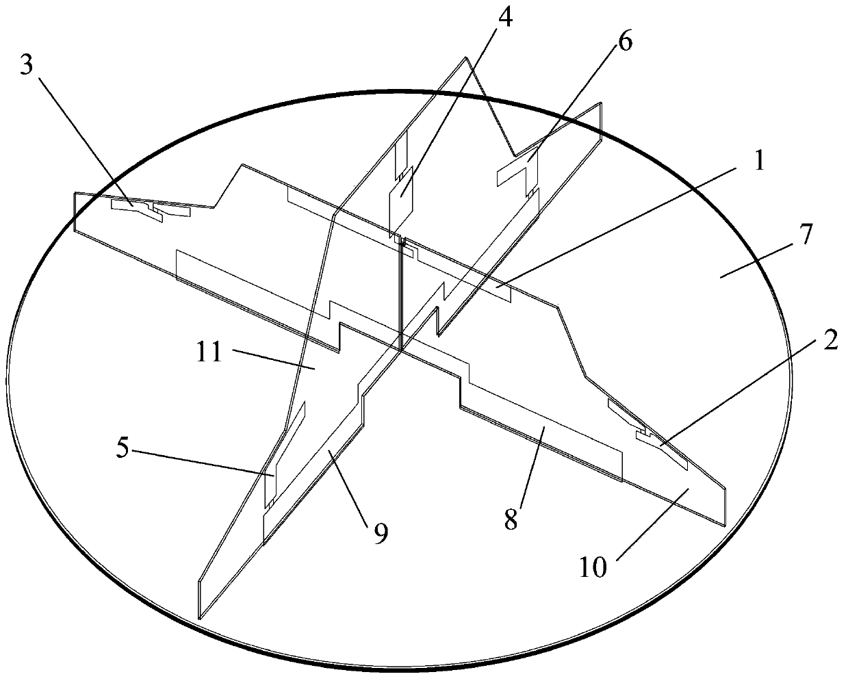
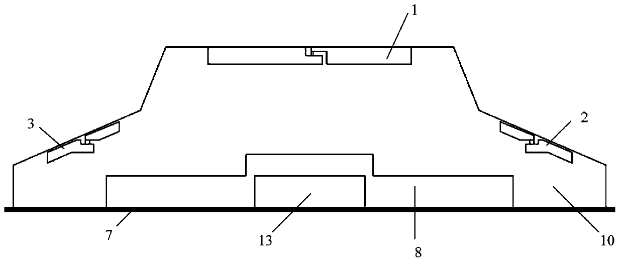
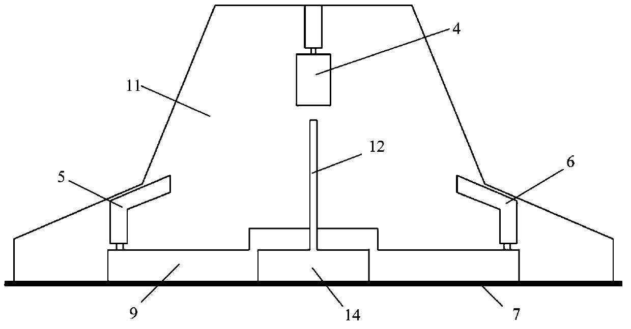
[0036] Such as figure 1 , figure 2 and image 3 As shown, the antenna includes a base plate 7, and a first dielectric plate 10 and a second dielectric plate 11 arranged crosswise, the first dielectric plate 10 and the second dielectric plate 11 stand on the base p...


PUM


Abstract

Disclosed in the invention is an omnidirectional antenna comprising a base plate, a first dielectric plate, and a second dielectric plate. The first dielectric plate and the second dielectric plate are arranged in an intersected mode and are vertically arranged on the base plate. The first dielectric plate includes a plurality of first polarons working at a first frequency band and the second dielectric plate includes at least one second polaron working at a second frequency band; and the polarization direction of one of the plurality of first polarons is different from those of other first polarons. According to the invention, because two groups of antennas are distributed in an intersected and staggered mode based on the novel layout and antennas with the same frequency use different polarization modes and structures, the isolation degree of the antennas is ensured and omnidirectional coverage is realized, so that mutual influence between the antennas can be avoided and thus the wireless transmission speed is improved to the greatest extent.

Description

technical field [0001] The present invention relates to the field of antennas, and in particular, to an omnidirectional antenna. Background technique [0002] The MIMO ceiling antennas on the market are all designed with metal radiators and metal backplanes, that is, using the antenna design principle of a monopole and a grounded backplane. Usually, three 2.4GHz monopole antennas and three 5.8GHz monopole antennas are divided into upper and lower layers inside the antenna. The upper layer layout is three co-polarized 5.8GHz monopole antennas and metal The isolation board is used to increase the isolation between antennas, and the lower layer is laid out in the same way as the upper layer, which are three co-polarized 2.4GHz monopole antennas. The characteristic of this layout is that a single antenna pattern on the same floor only covers 120 degrees, while three antenna patterns are superimposed to form a 360-degree omnidirectional antenna; the advantage is that the maximum...

Claims


Application Information

Patent Timeline
IPC IPC(8): H01Q1/52H01Q21/24H01Q21/30H01Q1/38H01Q1/12
Inventor 刘若鹏赵耀荣
Owner KUANG CHI INST OF ADVANCED TECH
Why Eureka
Try Eureka