A radio frequency power connector

A technology of radio frequency power supply and access device, which is applied to circuits, connections, contact parts, etc., can solve the problems of abnormal radio frequency circuit matching, damage to the radio frequency power generator, and poor heat dissipation performance of cables, so as to reduce the input impedance and improve the Effective output power and good heat dissipation performance

Active Publication Date: 2016-02-24
ENN SOLAR ENERGY
View PDF7 Cites 0 Cited by
  • Summary
  • Abstract
  • Description
  • Claims
  • Application Information

AI Technical Summary

Problems solved by technology

The matching of the RF circuit is abnormal, and the heat dissipation performance of the cable is not good, which affects the effective output power of the RF power supply, and may damage the RF power generator in serious cases

Method used


Image

  • A radio frequency power connector
  • A radio frequency power connector
  • A radio frequency power connector

Examples


Embodiment 1

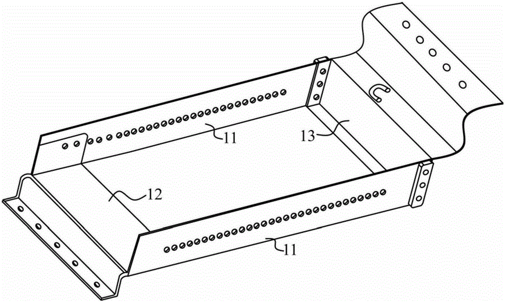
[0024] Such as figure 1 As shown, the first radio frequency access device 1 provided by the embodiment of the present invention specifically includes:

[0025] Two strip-shaped conductive plates 11, the first strip-shaped junction plate 12 for electrically connecting the RF power input end of the chemical vapor deposition PECVD equipment; and the second strip-shaped sink for electrically connecting the RF power output end of the RF power generator connecting plate 13; wherein:

[0026] Two strip-shaped conductive plates 11 are arranged opposite to each other, the two ends of the first strip-shaped connecting plate 12 are respectively connected to one end of a strip-shaped conductive plate 11, and the two ends of the second strip-shaped connecting plate 13 are electrically connected to a strip-shaped conductive plate 13 respectively. the other end of the board.

[0027] figure 1 Shown is a preferred example, the two strip-shaped conductive plates 11 are long strip conductors...

Embodiment 2

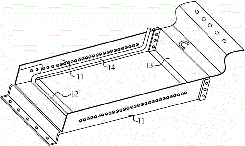
[0031] Such as figure 2 As shown, in order to further improve the heat dissipation capacity, each strip-shaped conductive plate 11 is also welded with a cooling liquid pipe 14 along the length direction. If the surfaces of the two strip-shaped conductive plates are relatively parallel, preferably, the cooling liquid pipe is welded on Each strip-shaped conductive plate 11 is located on a relatively parallel surface, that is, inside the frame-type connector. The two coolant pipes 14 can be as figure 2 The one shown is connected, that is, a heat dissipation pipe, and two ends are respectively connected with an adapter, which is used to connect the input pipe and the output pipe of the cooling liquid. The two cooling liquid pipes can also be independent, and an adapter is respectively connected to the two ends of each cooling liquid pipe, which are respectively used to connect the input pipe and the output pipe of the cooling liquid.

[0032] further as figure 1 with figure...

Embodiment 3

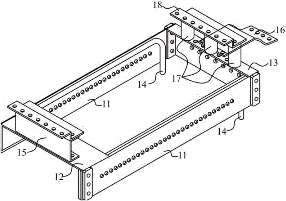
[0034] To further reduce the equivalent impedance, each strip-shaped conductive plate 11 can include a plurality of parallel conductive sub-plates, for example image 3 The two strip-shaped conductive sub-plates are shown in parallel and have a certain distance.


PUM


Abstract

The invention relates to electrical equipment, and discloses a radio frequency power supply access device, so as to improve effective output power of a radio frequency power supply generator to PECVD (plasma enhanced chemical vapor deposition) equipment. The radio frequency power supply access device comprises two bar-shaped current conducting plates, a first bar-shaped junction board used for being electrically connected with a radio frequency power supply input end of PECVD equipment, and a second bar-shaped junction board used for being electrically connected with a radio frequency power supply output end of a radio frequency power supply generator, both ends of the first bar-shaped junction board are connected with one ends of the bar-shaped current conducting plates, and both ends of the second bar-shaped junction board are electrically connected with the other ends of the other bar-shaped current conducting plates.

Description

technical field [0001] The invention relates to electrical equipment, in particular to a radio frequency power connector. Background technique [0002] Using a radio frequency power generator to generate plasma, as a chemical vapor deposition (PECVD) radio frequency power source connected to PECVD equipment, coating semiconductors, is one of the current mainstream semiconductor coating processes, and is widely used in liquid crystal panel manufacturing, Thin-film solar cell manufacturing and other related fields. [0003] The connection between the existing RF power generator and PECVD equipment is generally connected by cables between the RF power output of the RF power generator and the RF power input of the PECVD equipment. It is difficult to adjust the input impedance of the cable. The matching of the RF circuit is abnormal, and the heat dissipation performance of the cable is not good, which affects the effective output power of the RF power supply, and may damage the...

Claims


Application Information

Patent Timeline
Patent Type & Authority Patents(China)
IPC IPC(8): H01R13/00H01R13/02H01R31/06
Inventor 徐湛苗为民王青海
Owner ENN SOLAR ENERGY
Why Eureka
Try Eureka