
Optimal configuration method for high-voltage distribution network dynamic reactive power compensation equipment capacity

A compensation device and optimized configuration technology, applied in reactive power adjustment/elimination/compensation, special data processing applications, instruments, etc., which can solve problems such as difficulty in widespread use, large-capacity adoption, and high cost of dynamic reactive power compensation device equipment.

Inactive Publication Date: 2014-05-14
POWER DISPATCHING CONTROL CENT OF GUANGDONG POWER GRID CO LTD +1
View PDF2 Cites 18 Cited by
  • Summary
  • Abstract
  • Description
  • Claims
  • Application Information

AI Technical Summary

Problems solved by technology

The cost of dynamic reactive power compensation equipment is expensive, but the configuration conclusion has strong specificity, so it is difficult to adopt widely and in large capacity

Method used


Image

  • Optimal configuration method for high-voltage distribution network dynamic reactive power compensation equipment capacity
  • Optimal configuration method for high-voltage distribution network dynamic reactive power compensation equipment capacity
  • Optimal configuration method for high-voltage distribution network dynamic reactive power compensation equipment capacity

Examples


Embodiment Construction

[0023] The method of the present invention will be described in detail below in conjunction with the accompanying drawings.

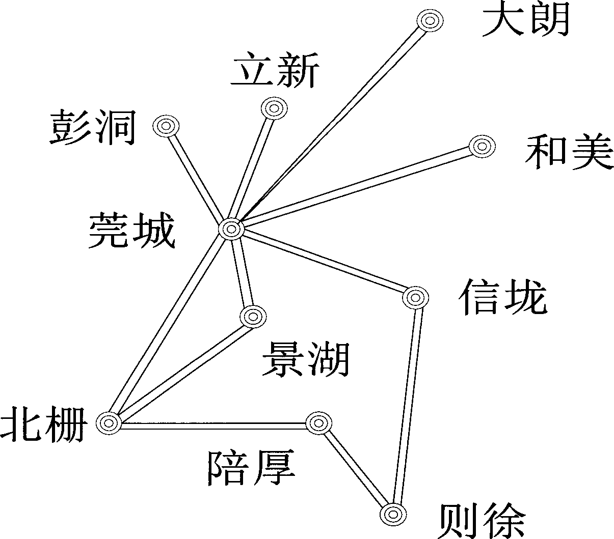
[0024] figure 1 The geographic wiring diagram of the high-voltage distribution network in the Guancheng area. This area is a typical 220kV area centered on the 500kV hub site in Guancheng, including nine 220kV sites.

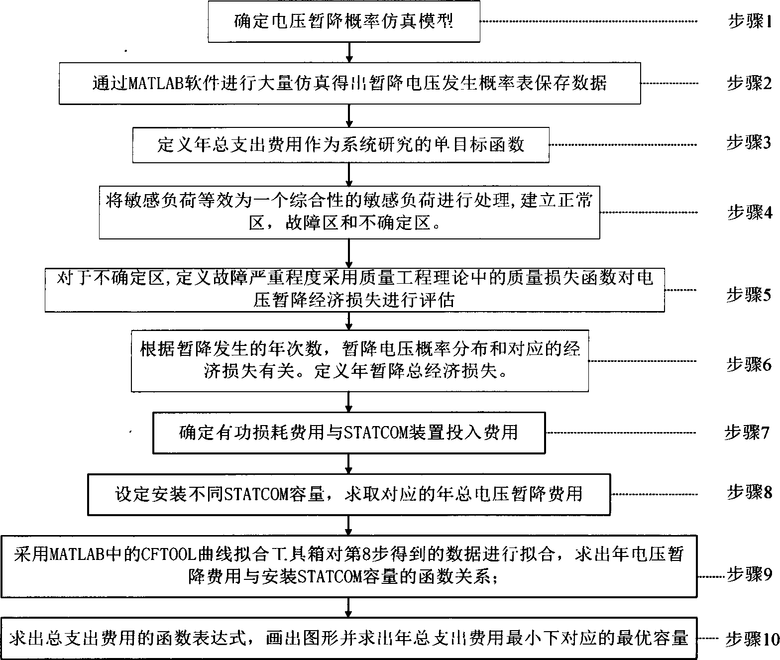
[0025] figure 2 Step 1 in the description is to determine the fault type, fault location, fault duration stochastic model.

[0026] In the high-voltage distribution network, with a continuous fault time of 5 cycles, it is determined that

[0027] Failure type probability model:

[0028]

[0029] In the formula: x is a randomly selected fault type variable

[0030] Failure location probability model:

[0031] F L = 1,0 y p l ...


PUM


Abstract

The invention discloses an optimal configuration method for high-voltage distribution network dynamic reactive power compensation equipment capacity. The optimal configuration method of the high-voltage distribution network dynamic reactive power compensation equipment capacity includes the steps that in a high-voltage distribution network, by combination of sensitive load characteristics, a voltage dip risk is introduced to serve as a voltage stabilization consideration object; a reactive power optimization single objective function model is established, and voltage dip loss, line active loss and dynamic reactive compensation equipment cost are added in an economic measurement mode; multiple groups of reactive capacity are set and corresponding total expenditure cost is solved; curve fitting is carried out on the cost and the capacity by means of MATLAB software, so that optimal capacity is calculated. According to the method, the modern power grid characteristic that a high-voltage distribution network voltage sensitive load continuously increases currently, the fact that the probability of voltage dips of a power grid is much larger than the probability of voltage collapse or the probability of voltage unstability, the situation that dynamic reactive compensation equipment configuration cost is relatively high currently and other actual influence factors are considered, and superiority is reflected from the perspectives of theories and engineering. Therefore, the method has a good actual instruction meaning.

Description

technical field [0001] The invention belongs to the technical field of electric power systems and automation thereof, and provides a method for optimal configuration of dynamic reactive capacity of a high-voltage distribution network. Background technique [0002] Traditional loads only consider whether the voltage is cut off or not. With the rapid development of science and technology, there are more and more sensitive loads, which also put forward higher requirements for voltage quality. As one of the most concerned dynamic power quality problems at present, voltage sag not only occurs frequently, but also causes huge economic losses to the system, especially sensitive loads. The Flexible AC Transmission System (FACTS) technology based on high-power power electronics is widely used in the power industry to enhance the stability and safety of power system operation, improve power transmission capacity and power efficiency, save energy and improve power Quality and other as...

Claims


Application Information

Patent Timeline
IPC IPC(8): H02J3/18G06F17/50
CPCY02E40/10
Inventor 辛拓杨银国李杰曹阳林建熙易扬
Owner POWER DISPATCHING CONTROL CENT OF GUANGDONG POWER GRID CO LTD
Learn More