
Wind farm group impedance analysis method, reactive power control method and device, and power generation system

A wind farm group, impedance analysis technology, applied in wind power generation, circuit devices, reactive power compensation, etc., can solve the problems of high cost, poor stability, poor coordination between centralized reactive power compensation equipment and wind turbines, etc., to reduce reactive power Losses and Active Losses, Economic Efficiency, Flexibility

Active Publication Date: 2020-09-08
BEIJING GOLDWIND SCI & CREATION WINDPOWER EQUIP CO LTD
View PDF5 Cites 0 Cited by
  • Summary
  • Abstract
  • Description
  • Claims
  • Application Information

AI Technical Summary

Problems solved by technology

When controlling each wind turbine itself, free control of the wind turbines in the wind farm will cause internal friction of the reactive power of the wind farm group, and the goal of giving priority to wind power generation efficiency cannot be achieved
When performing centralized reactive power compensation for wind farms, due to the disadvantages of high cost, large loss and poor stability of wind farm centralized reactive power compensation equipment, as well as the poor coordination between centralized reactive power compensation equipment and wind turbines, it cannot be done very well. Good realization of reactive power control

Method used

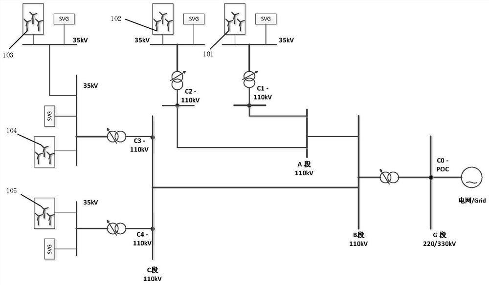
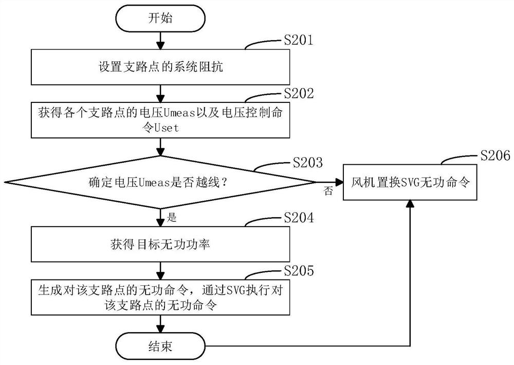

Image

  • Wind farm group impedance analysis method, reactive power control method and device, and power generation system
  • Wind farm group impedance analysis method, reactive power control method and device, and power generation system
  • Wind farm group impedance analysis method, reactive power control method and device, and power generation system

Examples


Embodiment Construction

[0077] The features and exemplary embodiments of various aspects of the present invention will be described in detail below. In order to make the objectives, technical solutions and advantages of the present invention more clear, the present invention will be further described in detail below with reference to the accompanying drawings and specific embodiments. It should be understood that the specific embodiments described herein are only configured to explain the present invention, and are not configured to limit the present invention. It will be apparent to those skilled in the art that the present invention may be practiced without some of these specific details. The following description of the embodiments is only intended to provide a better understanding of the present invention by illustrating examples of the invention.

[0078] It should be noted that, in this document, relational terms such as first and second are only used to distinguish one entity or operation from...


PUM


Abstract

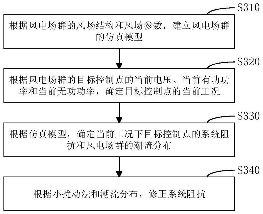
The invention discloses a wind power plant group impedance analysis method, a reactive power control method and device and a power generation system. A wind power plant group comprises a plurality ofwind power generator sets, wherein the plurality of wind power generator sets are connected to form a plurality of target control points, and each target control point comprises a grid-connected pointand a branch point of the wind power plant group. The wind power plant group impedance analysis method comprises the steps of building a simulation model of the wind power plant group according to awind field structure and a wind field parameter of the wind power plant group; determining a current working condition of the target control point according to a current voltage, a current active power and a current reactive power of each target control point of the wind power plant group; determining system impedance of the target control point and power flow distribution of the wind power plantfield under the current working condition according to the simulation model; and correcting system impedance according to a perturbation method and the power flow distribution. According to the wind power plant group impedance analysis method disclosed by the embodiment of the invention, the measurement error of system impedance can be reduced, and the flexibility of each wind power generator setcontrol and the safety and the stability of a power grid can be improved during reactive power control on the wind power plant group.

Description

technical field [0001] The invention belongs to the technical field of wind power, and in particular relates to a wind farm group impedance analysis method and a reactive power control method and device and a power generation system. Background technique [0002] In order to meet the increasing demand for power resources, the scale of wind farms needs to be increased. When the scale of the wind farm increases, not only the centralized access of large-scale wind turbines to the power system will have a great impact on the security and stability of the power grid, but also the fluctuation of the voltage at the grid connection point of the wind farm caused by the reactive power fluctuation will also directly affect The security and stability of the power grid. Specifically, as the scale of the wind farm increases, especially the capacity of the wind farm group increases, the output of the wind turbine will have a certain spatial coupling characteristic, so that the fluctuation...

Claims


Application Information

Patent Timeline
Patent Type & Authority Patents(China)
IPC IPC(8): H02J3/38H02J3/50H02J3/48H02J3/18
CPCH02J3/18H02J3/386H02J3/48H02J3/50H02J2203/20Y02A30/60Y02E10/76Y02E40/30
Inventor 闫虹肖迪张毅
Owner BEIJING GOLDWIND SCI & CREATION WINDPOWER EQUIP CO LTD
Learn More