
Seal structure using metal gasket

A metal gasket and sealing structure technology, which is applied in the direction of engine sealing, engine sealing device, engine components, etc., can solve the problems of easy corrosion and damaged sealing function, and achieve the effect of corrosion inhibition and low cost

Active Publication Date: 2014-05-14
NOK CORP
View PDF7 Cites 7 Cited by
  • Summary
  • Abstract
  • Description
  • Claims
  • Application Information

AI Technical Summary

Problems solved by technology

The metal gasket exerts the sealing function by the reaction force of the part in contact with the frame, but when the corroded part of the frame penetrates the sealing line, the sealing function is impaired
[0003] In addition, even if the frame is made of iron, corrosion occurs, but aluminum (Al) is particularly prone to corrosion because it is a metal with a greater tendency to plasma than iron (Fe).

Method used


Image

  • Seal structure using metal gasket
  • Seal structure using metal gasket
  • Seal structure using metal gasket

Examples


Embodiment

[0054] Embodiments of the present invention will be described below with reference to the accompanying drawings.

no. 1 example …

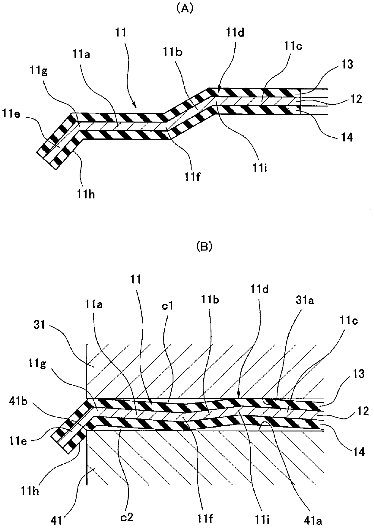
[0056] figure 1 (A) shows a cross-section of a main part of the metal packing 11 used in the sealing structure according to the first embodiment of the present invention, when the metal packing 11 is arranged on a pair of frames (housing or flanges) 31, 41, and if it is clamped (bolt tightened) in the thickness direction of the gasket (up and down in the figure), it becomes figure 1 (B) The fastened state is shown. The left side of each figure is the outer side (outer peripheral side) of the gasket 11 , that is, the sealing fluid side such as salt water, and the right side is the inner side (inner peripheral side) of the gasket 11 . Additionally, if figure 1As shown in (B), a pair of frame bodies 31 and 41 are formed by combining the frame body 31 on the upper side in the figure and the frame body 41 on the other side up and down in the figure. , 41a, install the metal liner 11. Although the frames 31 and 41 are made of aluminum, which is easily corroded by salt water, the...

no. 2 example …

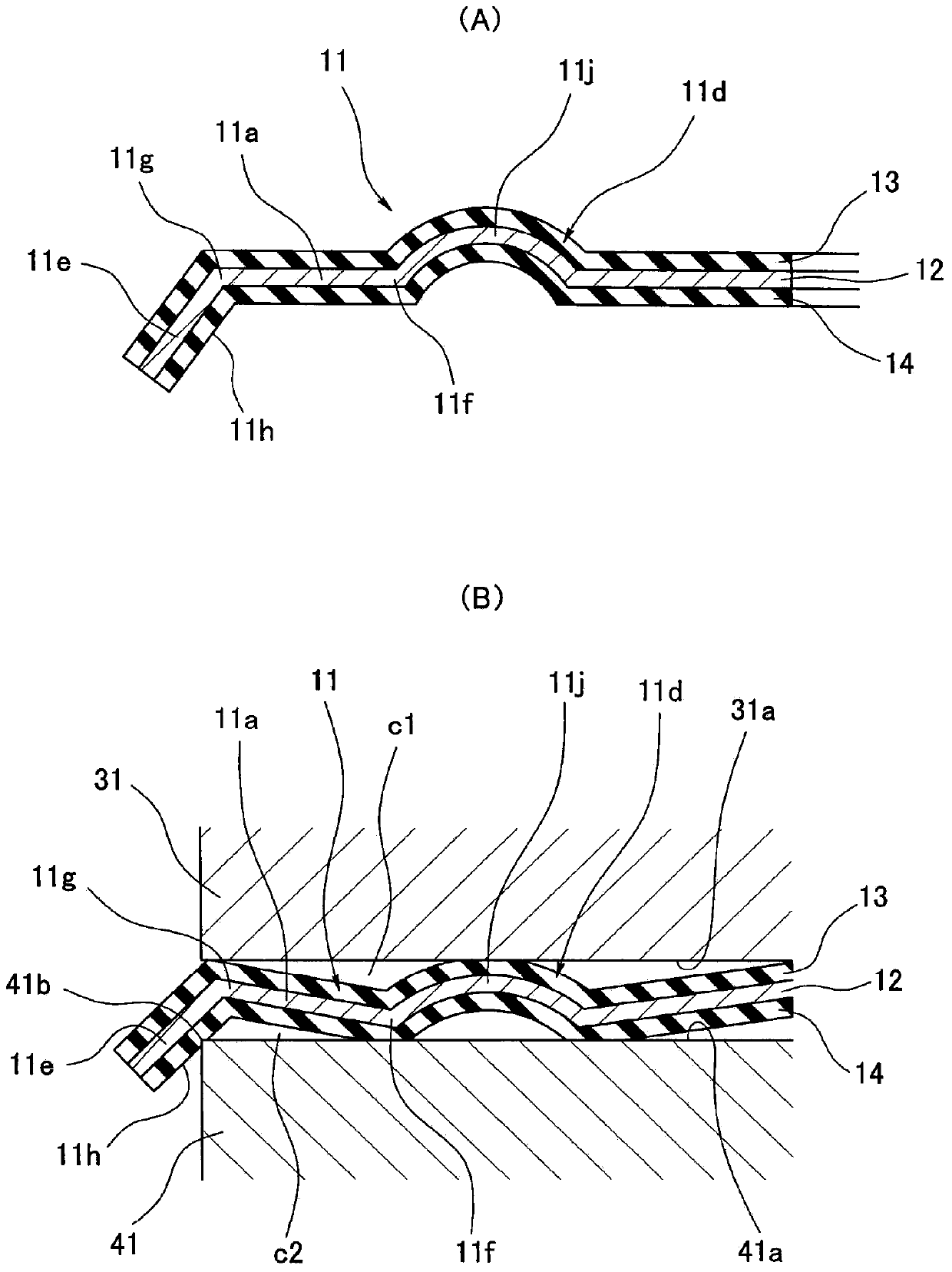
[0063] In the above-mentioned first embodiment, although the flange portion 11d of the metal backing 11 has a semi-flange shape formed by combining the inclined portion 11b and the inner peripheral portion 11c, the shape of the flange portion 11d is not particularly special. It can also be a full-flange shape such as an arc-shaped cross-section or a trapezoidal cross-section. An example of this is described below.

[0064] figure 2 (A) shows a cross section of a main part of the metal packing 11 used in the sealing structure according to the second embodiment of the present invention, when the metal packing 11 is arranged on a pair of frames (cases or flanges) 31 , 41, and if it is clamped (bolt tightened) in the thickness direction of the gasket (up and down in the figure), it becomes figure 2 (B) The fastened state is shown. The left side of each figure is the outer side (outer peripheral side) of the gasket 11 , that is, the sealing fluid side such as salt water, and t...


PUM


Abstract

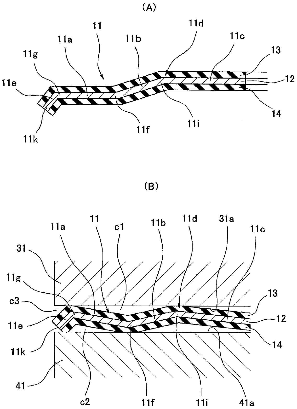
A seal structure is provided using a metal gasket. The structure substantially prevents formation of a gap that would allow salt water to collect between the metal gasket and a casing, thus suppressing corrosion of the casing due to the collection of salt water and allowing long-term maintenance of the seal function. To achieve this purpose, the metal gasket is arranged between a pair of casings. The metal gasket is provided with a bead on the inner circumference of a planar circumference part and a bent part on the outer circumference. When the metal gasket is compressed between the pair of casings, the bead elastically deforms so that the height of the bead is reduced and the outer circumference part elastically deforms accordingly, causing the outer edge of the circumference part to contact one of the casings, thereby preventing the formation of a gap that would allow salt water to collect between the casing and the outer circumference part. The bend-processed part contacts the other casing, thus providing a structure preventing formation of a gap that would allow salt water to collect between the other casing and the outer circumference part.

Description

technical field [0001] The present invention relates to a sealing structure utilizing a metal gasket. The sealing structure of the present invention is used in, for example, automobile-related fields or other fields. Background technique [0002] For example, in metal gaskets used in automobiles, salt spray tests may be performed as standard evaluation items (spec evaluation items) in preparation for driving in seaside areas or areas where deicing agents are sprayed in cold areas. In this case, if the frame on the target side to which the metal backing is attached is made of aluminum (including aluminum alloy, the same applies hereinafter), salt water will accumulate (adhere) in the gap between the metal backing and the frame, and due to repeated Dry and wet, therefore, corrosion (crevice corrosion) of aluminum due to salt water (difference in ion concentration) occurs. The metal gasket exerts a sealing function by the reaction force of the portion in contact with the fram...

Claims


Application Information

Patent Timeline
Patent Type & Authority Applications(China)
IPC IPC(8): F16J15/08
CPCF16J15/0818F16J2015/085F16J2015/0856F16J15/0825F02F11/00F16J15/0881
Inventor 安斋高纪丹治功中冈真哉伊藤胜当间将太
Owner NOK CORP
Learn More