Breathing electric motor

A motor and air guide technology, applied in the field of motors, can solve the problems of motor overheating, high development, production and storage costs, motor cooling performance heavily dependent on the direction of rotor rotation, etc.

Active Publication Date: 2014-05-14
BROSE FAHRZEUGTEILE GMBH & CO KG HALLSTADT (DE)
View PDF5 Cites 5 Cited by
  • Summary
  • Abstract
  • Description
  • Claims
  • Application Information

AI Technical Summary

Problems solved by technology

[0005] On the downside, the cooling performance of such self-cooling electric motors is heavily dependent on the direction of rotation of the rotor
This leads to different motor types being often developed and manufactured for applications with different main directions of rotation, which leads to

Method used


Image

  • Breathing electric motor
  • Breathing electric motor
  • Breathing electric motor

Examples


Embodiment Construction

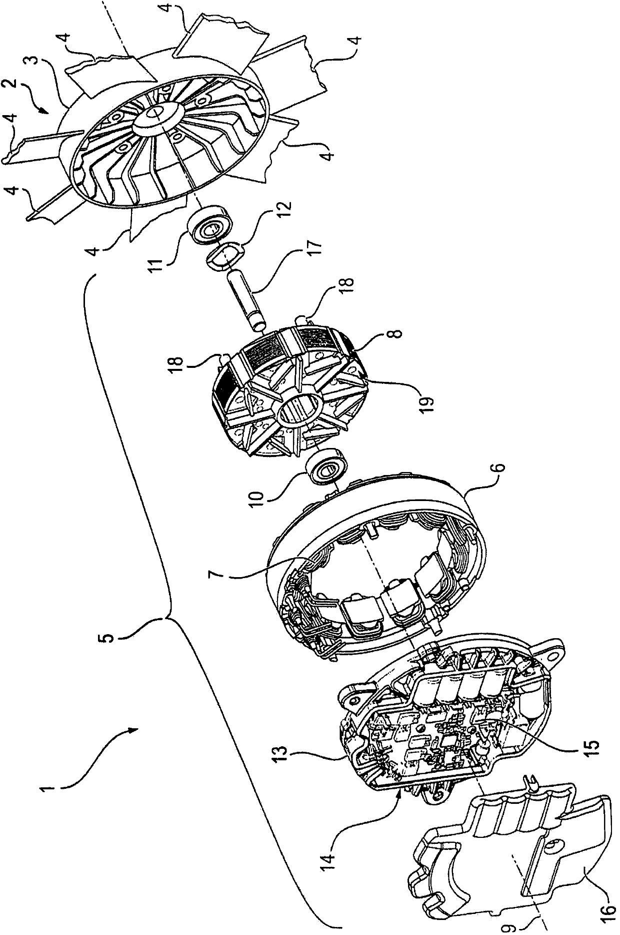
[0033] figure 1Fans 1 for a radiator of a motor vehicle are shown separated from one another. The fan 1 comprises a fan wheel 2 with a shroud 3 around the outer periphery of which seven (only the beginning is shown) air guide vanes 4 are evenly arranged. Furthermore, the fan 1 should comprise a (fan) motor 5 by means of which the fan impeller 2 is driven in rotation.

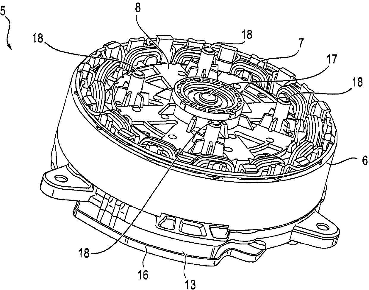
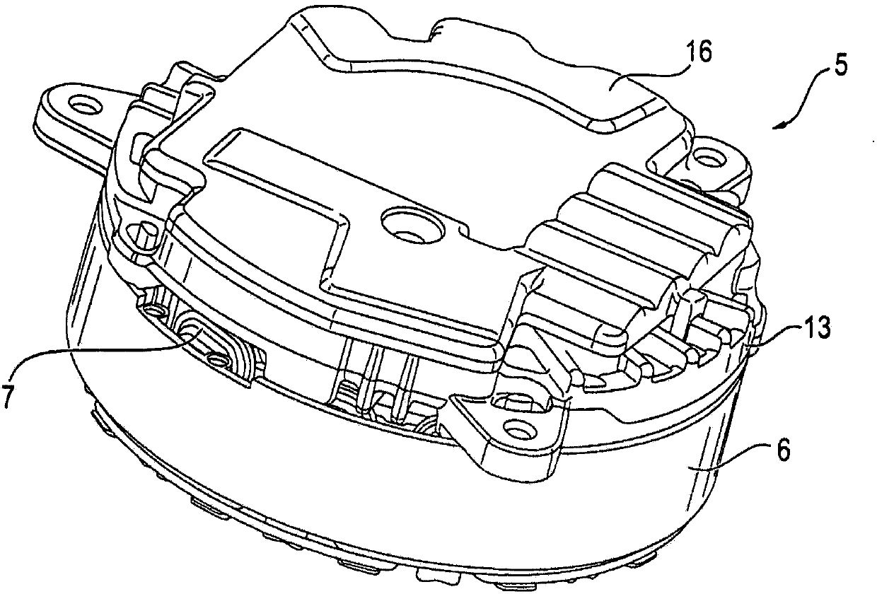
[0034] The electric machine 5 comprises a (hollow-cylindrical for simplicity) stator 6 , which is wound by a three-phase rotating field winding 7 . Furthermore, the electric machine 5 includes a (disc-shaped for simplicity) permanently excited rotor 8 , which is mounted rotatably about a machine axis 9 inside the stator 6 . To support the rotor 8 , the electric machine 5 includes two roller bearings 10 and 11 , which act on the rotor 8 from axially opposite sides. Here, the axial play of the rotor 8 between the two rolling bearings 10 and 11 is spring-loaded by means of spring coils 12 .

[0035] Furthermore...


PUM


Abstract

The invention relates to an electric motor (5) that has efficient self-cooling. The electric motor (5) comprises a rotor (8) that is rotatably mounted with respect to a stator (6). On a first sub-segment (23a) of an end face (19) of the rotor (8), a first air-guiding contour (20a) is formed that, during rotation of the rotor (8) in a reference rotation direction (R), generates an outwardly directed air flow (S). On a second sub-segment (23b) of the same end face (19), a second air-guide contour (20b) is formed that, during rotation of the rotor (8) in a reference rotation direction (R), generates an inwardly directed air flow (S).

Description

technical field [0001] The invention relates to a motor, especially a self-cooling brushless motor. Background technique [0002] Electric motors generally comprise a rotor (or mover) that is rotatably mounted relative to a stationary stator (or stator). In brushless motors, the stator is usually equipped with a rotating field winding through which a rotating field is generated by applying an alternating current to the rotating winding. The rotor, which is often arranged inside the stator, is generally equipped with permanent magnets, which generate an excitation field that interacts with the rotating magnetic field of the stator. [0003] In brushless motors, the alternating current provided for supplying the stator windings is usually generated by means of inverter electronics (also referred to below as inverter). In smaller electric motors, the inverter is often accommodated together with the associated control electronics in an electronics compartment which is integrat...

Claims


Application Information

Patent Timeline
IPC IPC(8): H02K9/06H02K11/00
CPCH02K1/22H02K3/522H02K5/10H02K11/33H02K9/06H02K9/00H02K5/207H02K1/2706H02K1/32
Inventor 托比亚斯·希伦布兰德
Owner BROSE FAHRZEUGTEILE GMBH & CO KG HALLSTADT (DE)
Why Eureka
Try Eureka