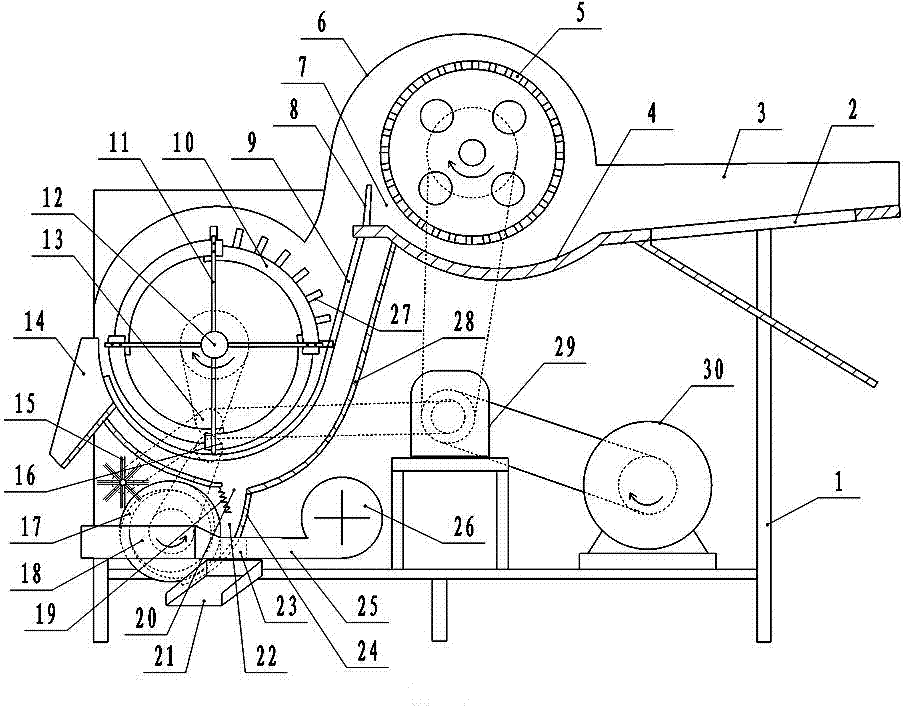
[0003] Aiming at the problem in the prior art that the removal efficiency of the chestnut bracts in the secondary separation device is not high, and debris is mixed into the output end of the chestnut, the present invention provides an auger-type chestnut
bract stripping machine. The machine is composed of a frame, a shell, a rolling device, a separation device, a discharge device and a power device. The rolling device is composed of a mesh-shaped pressing roller and an arc-shaped backing plate. The two ends of the rotating shaft of the pressing roller are installed on the frame. In the middle of the upper part, the backing plate is installed under the pressure roller. The front end of the pressure roller is equipped with a feed plate, and the rear end is designed with a crushed material outlet. One end is small; the separation device is installed under the crushed material outlet of the rolling device; the rolling device and the separation device are installed in the shell; the discharge device is installed under the separation device, and the discharge device consists of a screw output roller, a discharge pad, It is composed of chestnut output port and slag
brush. The two ends of the spiral output roller shaft are installed on the frame. The discharge backing plate is arc-shaped and installed on one side of the screw output roller. Fitting, the chestnut output port is designed on the side of the gap between the screw output roller and the discharge backing plate, the slag
brush is installed on the side above the screw output roller, and the bristles of the slag brush are in
close contact with the surface of the screw output roller; the
power unit is installed on the On the frame below the pressure roller, the driving motor of the
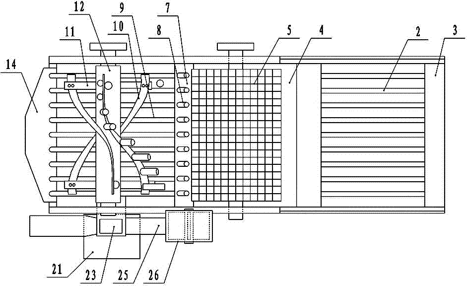
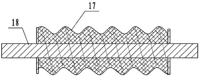
power unit is connected to the gearbox with a chain, and the gearbox is connected with the rotating shaft of the pressure roller with a chain; It is composed of struts, twisted plates and cleaning rods of the drain grid. The two ends of the auger shaft are installed on the frame, and the two ends of the auger shaft are radially fixed with "ten"-shaped struts. The two ends of the
winch are installed at intervals on the ends of the two struts at both ends of the shaft of the auger, and the chestnut drain grid is installed on one side of the
circular motion track of the winch, and its lower end is arc-shaped, extending and wrapping to the twister. On the
lower half circumference of the plate, the distance between the chestnut drain grids is greater than the
diameter of one chestnut, and smaller than the
diameter of two chestnuts. On the side of a twisted plate, a cleaning rod for the drain grid is installed, and the cleaning rod rotates from the chestnut drain grid. The bottom plate is installed under the chestnut drain grid, and a chestnut drop trough is designed at the bottom of the bottom plate. The gap between the spiral output roller and the discharge backing plate is located under the chestnut drop slot, and the chestnut drop grid is located at the bottom of the chestnut drain grid. There is a thorn bud outlet installed on one side, and a set of direction-changing gears are installed on the side of the frame. The gearbox is connected with the upper gear of the direction-changing gear with a chain, and the upper gear of the direction-changing gear is connected with the rotating shaft of the twist plate and the rotating shaft of the slag brush with a chain. , the lower gear of the reversing gear is connected to the shaft of the spiral output roller with a chain

